- Services tab
- Services (2) tab
- RX mode
- TX mode
In the Services tab, individually select and define the settings for Services 0, Services
1, Services 2, Services 3 and Services 4. While the settings for the Service 0 and
Service 2 are contained in the EEPROM, the settings for Service 3 and Service 4 are in
SRAM. During the export of the settings into a *.hex programming file,
the file saves only the EEPROM values, whereas, the *.xml file saves
all the settings. In addition, export all configuration settings as *.h
files, which include C code declarations for a global variable array within the
initialization data. This allows loading the settings from a host controller using the
SPI link or from within a Flash application program.
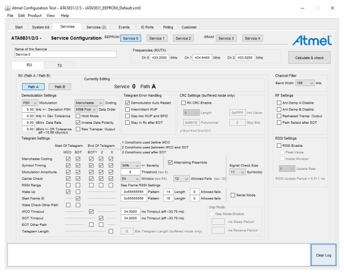
The RX (Path A/Path B) settings are divided into settings for Path A and Path B. With these separate settings, it is possible to work with two individual configurations in parallel. After entering the settings into the EEPROM configuration tool, click the Calculate & Check button to perform a consistency check. The Log window at the bottom displays the results and any other errors. For more details on the EEPROM service configuration, refer to the ATA8510/15 Industrial User's Guide (DS50003142).
Select the appropriate service and channel, when issuing a Set System Mode command via SPI command or from inside a Flash application, or when selecting an operating mode for the system start (except IDLE mode). For more details about the default settings, refer to Default Configuration.
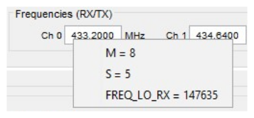
- Main Counter (M) = 8 – Frequency parameter for the fractional-n divider
- Swallow Counter (S) = 5 – Frequency parameter for the fractional-n divider
- FREQ_LO_RX = 147635 – Local
oscillator RX frequency parameter
Note: For more details about the above parameters, refer to the ATA8510/15 Industrial User's Guide (DS50003142).
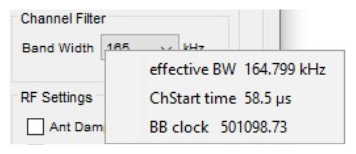
- effective BW = 164.799 kHz – True bandwidth setting
- ChStart time = 58.5 µs – Channel filter start-up time
- BB clock = 501098.90 – Channel
filter base band clock
Note: For more details about the above parameters, refer to the ATA8510/15 Industrial User's Guide (DS50003142).
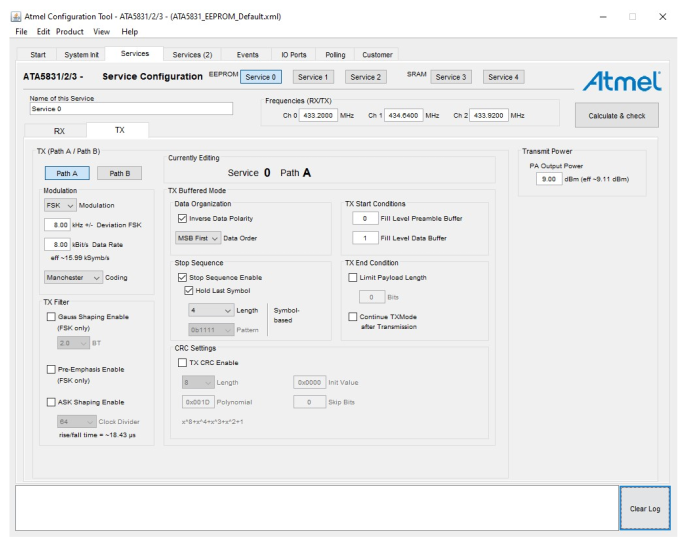
The following figure illustrates the TX settings, which are further divided into settings for Path A and Path B.
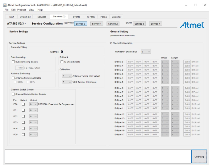
The following figure illustrates the continuation of Service Configuration within the Services (2) tab. The Services (2) tab continues the RX settings for Service 0, Service 1, Service 2, Service 3 and Service 4, and also includes the “Channel Switch Control”. The “Channel Switch Control” section permits the use of the port C pins for an external RF switch. These settings are specific for each individual service, so configure the I/O pins from port C to either low or high level.
For each service, check the ID Check Enable option under the ID Check field. The ID check is a general setting for all services. For more details on the EEPROM ID byte configuration, refer to the ATA8510/15 Industrial User's Guide (DS50003142).