The 16-bit Timer/Counter unit allows accurate program execution timing (event management), wave generation, and signal timing measurement. Most register and bit references in this section are written in general form. A lower case “n” replaces the Timer/Counter number, and a lower case “x” replaces the Output Compare unit channel. However, when using the register or bit defines in a program, the precise form must be used i.e., TCNT1 for accessing Timer/Counter1 counter value and so on.
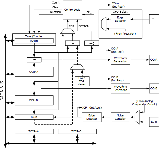
A simplified block diagram of the 16-bit Timer/Counter is shown in the following figure. For the actual placement of I/O pins, refer to Pin Configurations. CPU accessible I/O Registers, including I/O bits and I/O pins, are shown in bold. The device-specific I/O Register and bit locations are listed in the Register Description.