The temperature indicator module consists of a temperature-sensing circuit that provides a voltage to the device ADC. The analog voltage output varies inversely to the device temperature. The output of the temperature indicator is referred to as VMEAS.
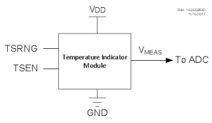
The following figure shows a simplified block diagram of the temperature indicator module.
The output of the circuit is measured using the internal Analog-to-Digital Converter. A channel is reserved for the temperature circuit output. Refer to the “ADCC - Analog-to-Digital Converter with Computation Module” chapter for more details.
The ON/OFF bit for the module is located in the FVRCON register. The circuit is enabled by setting the TSEN bit. When the module is disabled, the circuit draws no current. Refer to the “FVR - Fixed Reference Voltage” chapter for more details.