It is important to match components like an antenna, Surface Acoustic Wave (SAW) filter, Low
Noise Amplifier (LNA), switches and other components as all of these components have a
specific impedance. This impedance is mainly driven by the internal architecture and
parasitic inside of the circuit. According to the maximum power transfer (Jacobi’s law)
theorem, the maximum power is reached if the load resistance is equal to the resistance
of the source (see the following figure).
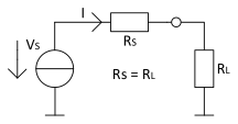
Figure 1. Equivalent Circuit Diagram for
Maximum Power Transfer
RS – Resistance of the source
RL – Resistance of the load
Note: It is useful to have a standardized
value of impedance for every component. It is very common that most of the test
equipment, including some RF components, have an input impedance of 50Ω.
This standardized value minimizes the loss in RF signal transfer, but not every component can be
designed with a 50Ω impedance, and not every component has a real impedance. Inductive
and capacitive influences result in a complex impedance consisting of a real and an
imaginary part. In the case of a complex impedance, the maximum power transfer theorem
must be extended so that the impedance of the load is equal to the complex conjugate
impedance of the source. If this is true, the imaginary influences are eliminated and
the real impedance remains. The following figure shows the equivalent circuit diagram
for complex conjugate matching.
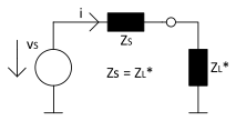
Figure 2. Equivalent Circuit Diagram for
Complex Conjugate Matching
ZS – Source impedance
ZL* – Load impedance (complex conjugate source impedance)