To demonstrate features like POR, BOD, and VLM in a realistic manner, a board controller is necessary to control the operating voltage of the ATtiny3217 device. Based on user input, implemented using a touch slider, the board controller will regulate the voltage supplied to ATtiny3217. With this setup, the user can adjust the slider and see the functionality of the POR, BOD, and VLM features and see the respective LEDs get set or cleared in the Reset Register, shown in Figure 1, based on what type of reset the device experienced on the previous reset.

The board controller drives the status LEDs to indicate the voltage level supplied to ATtiny3217.
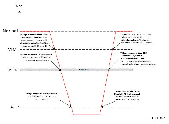
The different states are the following:
Normal
The operating voltage is set to approx. 5V and the Normal LED is set. The application heartbeat is stable at 60 beats per minute (bpm), as long as there are no other errors.
Voltage Level Monitor (VLM)
The operating voltage is set slightly (<15%) above the BOD level of ATtiny3217, and the VLM LED is set. The application heartbeat will increase to 90 bpm to indicate to the user that the VLM interrupt has triggered.
Brown-out Detect (BOD)
The operating voltage is set below the BOD level of ATtiny3217, and the BOD LED is turned ON. As the supplied voltage is below the BOD level, the BOD holds ATtiny3217 in reset. The application is not running and the application heartbeat is off.
Power-on Reset (POR)
The operating voltage is set below the POR threshold of ATtiny3217, and the POR LED is turned ON. As the supplied voltage is below the POR level, the POR holds ATtiny3217 in reset. The application is not running and the application heartbeat is off.