The Serial Clock (SCL) signal is generated by module hardware via the I2C Clock Selection (I2CxCLK) Register, the I2C Baud Rate Prescaler (I2CxBAUD) Register, and the Fast Mode Enable (FME) bits. This differs from the MSSP configuration which uses the Synchronous Serial Port Mode Select (SSPM) bits and the MSSP Baud Rate Divider and Address (SSPxADD) register to generate the SCL signal.
The figure below illustrates the SCL clock generation.
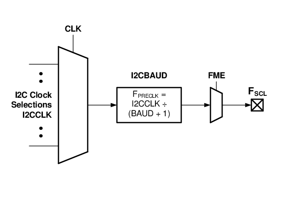
I2CxCLK contains several clock source selections. The clock source selections typically include variants of the system clock and timer resources.
I2CxBAUD is used to determine the prescaler (clock divider) for the I2CxCLK source.
The FME bits act as a secondary divider to the prescaled clock source.
The equation below shows the method to calculate the SCL frequency.
When FME = 00, one SCL period (TSCL) is equal to five clock
periods of the prescaled I2CxCLK source. In other words, the prescaled I2CxCLK source is
divided by five. For example, if the HFINTOSC (set to 4 MHz) clock source is selected,
I2CxBAUD is loaded with a value of ‘7’ and the FME bits are clear, the
actual SCL frequency is 100 kHz (SCL Frequency (FME = 00)).
SCL Frequency (FME =
00)
- I2CxCLK: HFINTOSC (4 MHz)
- I2CxBAUD:
7 - FME:
00
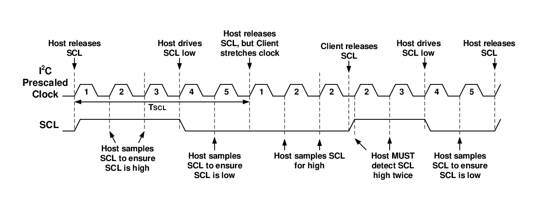
When FME = 00, host hardware uses the first prescaled I2CxCLK source
period to release SCL, allowing it to float high (Figure 3). Host hardware then uses the second and third periods to sample SCL
to verify that SCL is high. If a client is holding SCL low (clock stretch) during the
second and/or third period, host hardware samples each successive prescaled I2CxCLK
period until a high level is detected on SCL. Once the high level is detected, host
hardware samples SCL during the next two I2CxCLK periods to verify that SCL is high. The
host hardware then uses the fourth prescaled I2CxCLK source period to drive SCL low.
During the fifth period, host hardware verifies that SCL is in fact low.
00)
When FME = 01, one SCL period (TSCL) is equal to four clock
periods of the prescaled I2CxCLK source. In other words, the prescaled I2CxCLK source is
divided by four. Using the example from above, if the HFINTOSC (4 MHz) clock source is
selected, I2CxBAUD is loaded with a value of ‘7’, and FME =
01, the actual SCL frequency is 125 kHz (SCL Frequency (FME = 01)).
SCL Frequency (FME =
01)
- I2CxCLK: HFINTOSC (4 MHz)
- I2CxBAUD:
7 - FME:
01
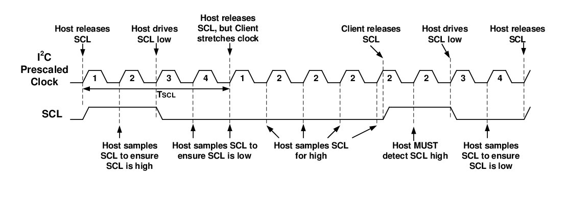
When FME = 01, host hardware uses the first prescaled I2CxCLK source
period to release SCL, allowing it to float high (Figure 4). Host hardware then uses the second period to sample SCL to verify
that SCL is high. If a client is holding SCL low (clock stretch) during the second
period, host hardware samples each successive prescaled I2CxCLK period until a high
level is detected on SCL. Once the high level is detected, host hardware samples SCL
during the next period to verify that SCL is high. The host hardware then uses the third
period to drive SCL low. During the fourth prescaled period, host hardware verifies that
SCL is in fact low.
01)
When FME = 10, one SCL period (TSCL) is equal to sixteen
clock periods of the prescaled I2CxCLK source. In other words, the prescaled I2CxCLK
source is divided by 16. In SCL Frequency (FME = 10), when the HFINTOSC (64 MHz) clock source is selected, I2CxBAUD is
loaded with a value of ‘3’, and FME = 10, the actual
SCL frequency is 1 MHz.
SCL Frequency (FME = 10)
- I2CxCLK: HFINTOSC (64 MHz)
- I2CxBAUD:
3 - FME:
10
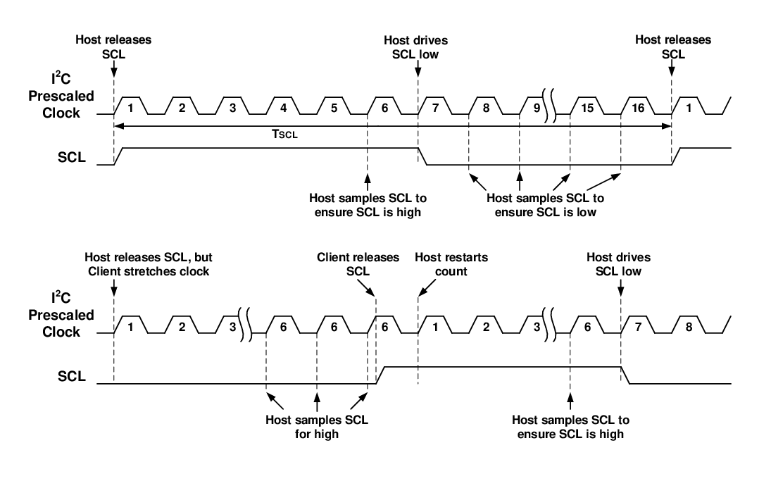
When FME = 10, host hardware uses the first prescaled I2CxCLK source
period to release SCL, allowing it to float high (Figure 5). Host hardware then uses the sixth period to sample SCL to verify
that SCL is high. If a client is holding SCL low (clock stretch) during the sixth
period, host hardware samples each successive prescaled I2CxCLK period until a high
level is detected on SCL. Once the high level is detected, host hardware samples SCL
during the next six I2CxCLK periods to verify that SCL is high. The host hardware then
uses the seventh prescaled I2CxCLK source period to drive SCL low. During eighth through
sixteenth periods, host hardware verifies that SCL is in fact low.
10)
The following tables show the different FME Bit Options and Common I2CBAUD Divider Settings for different modes of I2C operation.
| I2C Mode | Valid FME Bit Options |
|---|---|
| Standard mode (Max fSCL = 100 kHz) | FME = 00, 01,
10 |
| Fast mode (Max fSCL = 400 kHz) | FME = 01, 10 |
| Fast mode plus (Max fSCL = 1 MHz) | FME = 10 |
|
I2CxCLK Osc Freq |
fSCL = 1 MHz FME = |
fSCL = 400 kHz FME = |
fSCL = 100 kHz FME = |
fSCL = 10 kHz FME = |
|---|---|---|---|---|
| I2CxBAUD Values | ||||
| 64 MHz | 3 | 39 | 159 | - |
| 32 MHz | 1 | 19 | 79 | - |
| 16 MHz | 0 | 9 | 39 | - |
| 8 MHz | - | 4 | 19 | 199 |
| 4 MHz | - | - | 9 | 99 |
| 2 MHz | - | - | - | 49 |
| 1 MHz | - | - | - | - |
| 500 kHz | - | - | - | - |