Edge Triggering
The edge triggering mechanism is looking for the signal to cross the trigger level. For a positive edge trigger, the signal must go from below the trigger level, to above the trigger level.
Figure 1. Positive Edge
Trigger
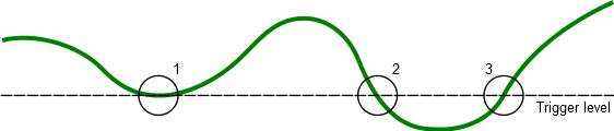
- No trigger – the line must cross.
- No trigger – wrong direction.
- Trigger point.
Figure 2. Negative Edge
Trigger
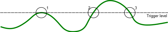
- No trigger – the line must cross.
- No trigger – wrong direction.
- Trigger point.

