
5.1 Die Drawing
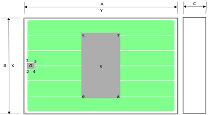
| Key | Dimensions | |||||
|---|---|---|---|---|---|---|
| Inch | Inch | Micrometer | Micrometer | Tolerance | Tolerance | |
| X | Y | X | Y | Inch | Micrometer | |
| 1 | 0 | 0 | 0 | 0 | ±0.0002 | ±5 |
| 2 | 0.01622 | 0 | 412 | 0 | ±0.0002 | ±5 |
| 3 | 0 | 0.01606 | 0 | 408 | ±0.0002 | ±5 |
| 4 | 0.01622 | 0.01606 | 412 | 408 | ±0.0002 | ±5 |
| 5 | 0.08047 | 0.12012 | 2044 | 3051 | ±0.0002 | ±5 |
| 6 | 0.09669 | 0.12012 | 2456 | 3051 | ±0.0002 | ±5 |
| 7 | 0.08047 | 0.20673 | 2044 | 5251 | ±0.0002 | ±5 |
| 8 | 0.09669 | 0.20673 | 2456 | 5251 | ±0.0002 | ±5 |
| A | 0.3431 | 8714 | ±0.0079 | ±200 | ||
| B | 0.2631 | 6684 | ±0.0079 | ±200 | ||
| C | 0.0150 | 381 | ±0.0010 | ±25 | ||
Note:
- Dimensions are in inches. Micrometers are given for general information only.
- All dimensions are valid for all radiation hardness levels specified
- For sawn die, outline dimensions (A and B) will be reduced by 0.001 inches (25 µm), due to saw kerf
- Die bond pad coordinates are provided for use in automated bonding equipment. Key locations 1 through 4 refer to adjacent gate (G) pad corners. Key locations 5 through 8 refer to adjacent source (S) pad corners.
- Keys 2 through 8 are relative to Key 1
- Top metal: Titanium, Titanium Nitride, 1000 Å; Aluminum Copper (0.5%), 45,000 Å
- Back metal: Titanium, Nickel, Silver 700 Å, 3200 Å, 7500 Å thick, respectively
- Backside metal is the drain connection