8.2 Example
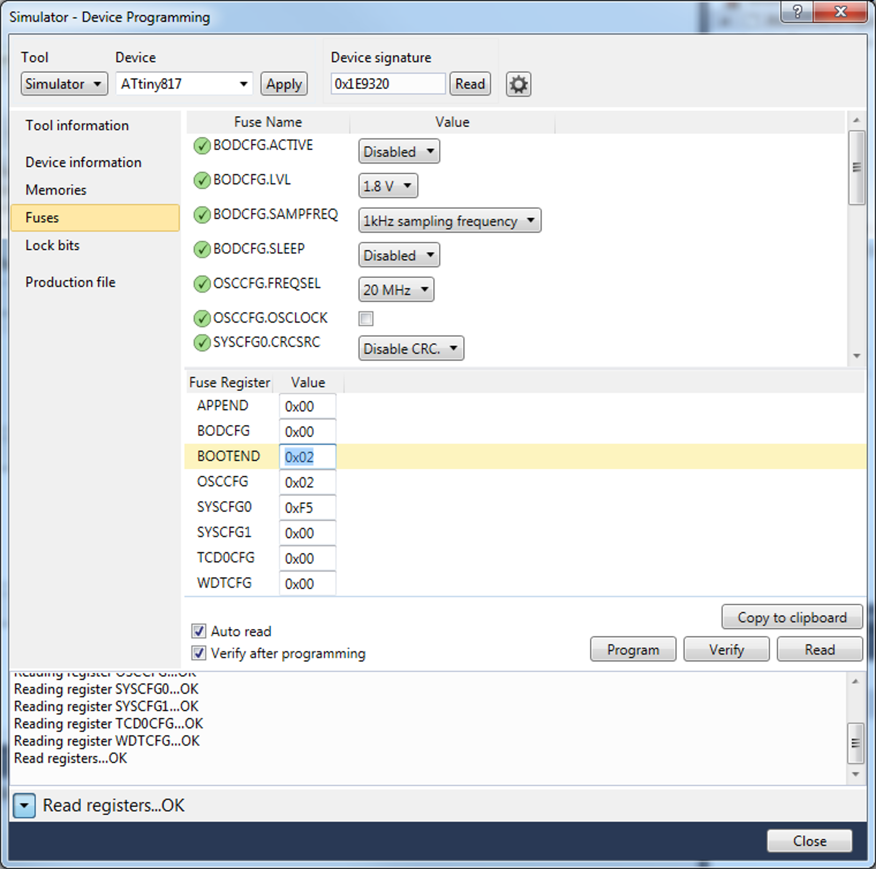
This example will use a bootloader section with 512 bytes size. This means the BOOTEND fuse needs to be configured to 512/256 = 0x02. In Atmel Studio 7.0 this fuse can be written to the device using Device Programming (Ctrl+Shift+P) - Fuses, as seen in Figure 8-1.

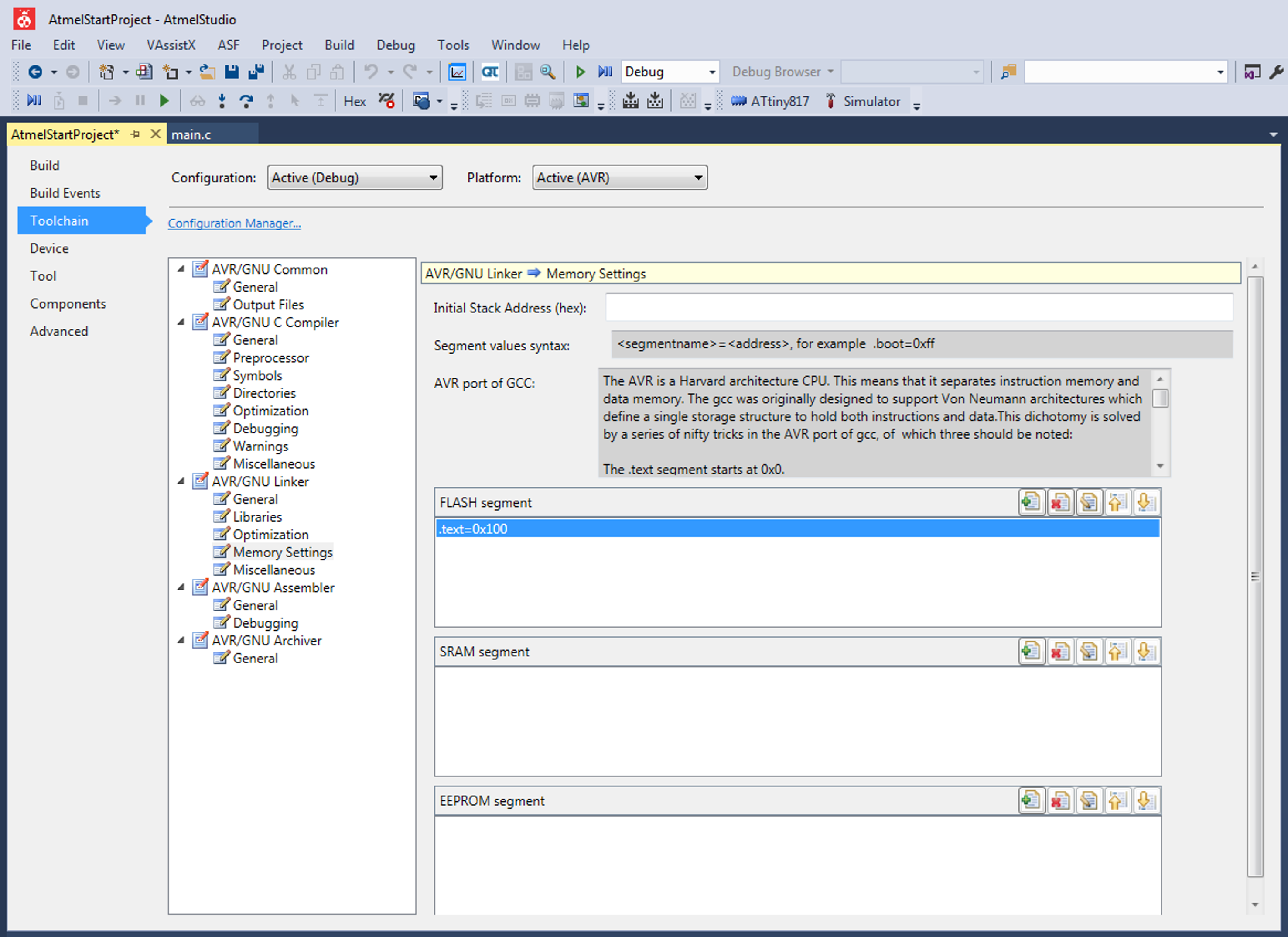
The AVR® GCC project must also be configured to shift the start of the application section by 512 bytes. This is done by changing the start of the text segment in the linker, and this value must be set in hexadecimal word size, for example: -Wl,-section-start=bootloader=0x100. In Atmel Studio 7.0 this can be found in Project Properties (Alt+F7) - Toolchain - AVR/GNU Linker - Memory Settings and adding .text=0x100 to the FLASH segment, as seen in Figure 8-2.

The following code example shows how to relocate the vector table.
// io.h includes the device header file with register and vector defines,
// it also includes xmega.h, containing the CCP macro _PROTECTED_WRITE().
#include <avr/io.h>
// interrupt.h contains the ISR related content
#include <avr/interrupt.h>

void relocating_vector_table_example(void) {
    // Set the Interrupt Vector Select bit,
    // read-modify-write to preserve other configured bits
    _PROTECTED_WRITE(CPUINT.CTRLA, (CPUINT.CTRLA | CPUINT_IVSEL_bm));

    //Enable global interrupts
    sei();
}

ISR(PORTA_PORT_vect){
    // After setting the IVSEL bit, the interrupt vector table
    // will now be shifted from BOOTEND*256 bytes to start of Flash (0x0000).

    // When using an interrupt in the application code, IVSEL must be cleared and
    // the code compiled with the .text section in Flash set to BOOTEND*128 words.
}
