Debug GPIO channels are timestamped digital signal lines connecting the target
application to a host computer visualization application. They are typically used to
plot low-frequency events on a time axis, such as when given Application state
transitions occur.
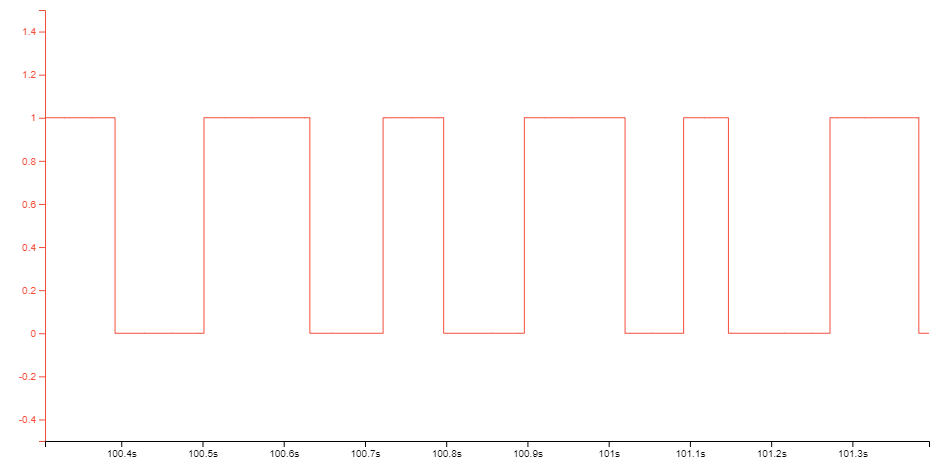
The figure below shows the monitoring of the Digital state of a mechanical switch
connected to a debug GPIO in MPLAB Data Visualizer.Figure 3-2. Monitoring Debug GPIO with
MPLAB Data Visualizer
Debug GPIO channels are timestamped, so the resolution of DGI GPIO events is determined
by the resolution of the DGI Timestamp module.
Important: Although signal
bursts of higher frequency can be captured, the frequency range of signals for which
debug GPIO can be used is up to about 2 kHz. Attempting to capture signals above
this frequency will result in data saturation and overflow, which may cause the DGI
session to be aborted.
The online versions of the documents are provided as a courtesy. Verify all content and data in the device’s PDF documentation found on the device product page.