
2 MCC Melody DV Run Time Configuration
2.1 Builder: Add DV Run Time Library
Application Builder: Click 'Add Component'.
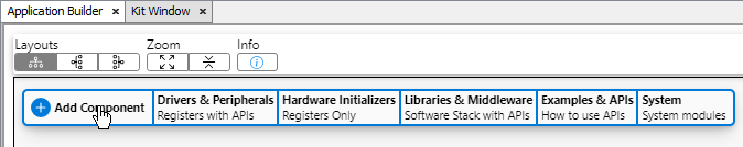
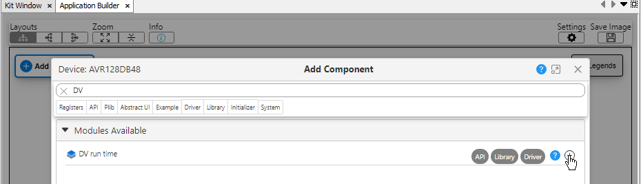
Filter on 'Data' then click the  icon to add the DV Run Time.
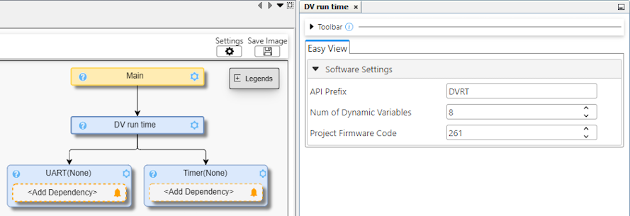
- Timer Dependency Selection: Select any available timer. The Timer driver default of 1 ms, with interrupts enabled is used.
- UART Dependency Selection: Determine the UART instance connected to
your computer's COM port, which could be a Virtual Serial Port (CDC). Check
the board layout schematic on the MCU side to find the UART instance and the
Device Manager for Windows or on a Mac terminal type
ls
                            /dev/tty.*
to find which serial port the UART is connected to.Note: CDC refers to USB Communications Class Device.Note: For Curiosity Nano boards, this is usually the UART instance connected to the debugger. Using USB-to-Serial bridges will also work. Here, the Data Visualizer will automatically detect the COM port of the connected kit.Note: UART Software Receive Buffer Size is calculated by the DV Run Time Library: Receive buffer for DVRT Frame needs to fit the largest command, i.e., UpdateVariablePtrTableCmd, which is 28 bytes by default, when NumVars is 8. Frame calculation: Start_Byte + Cmd_Byte + NumVars_Byte + (NumVars * 3 Bytes) + End_Byte.
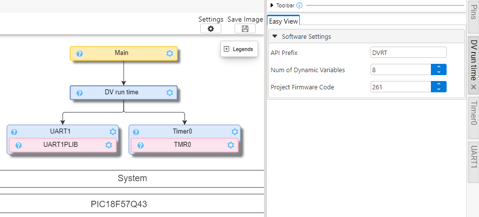
2.2 Builder: Select UART and Timer Dependencies
2.3 Pins Selection: Finding Schematics
To select any of the required pins for a given example, refer to the schematic of the board you are using. Examples can often be run on a range of hardware, selecting appropriate pins for a LED, Analog Input (ANx), UART Tx/Rx, etc.
If the Curiosity Nano platform is being used, the following guidelines will be useful.
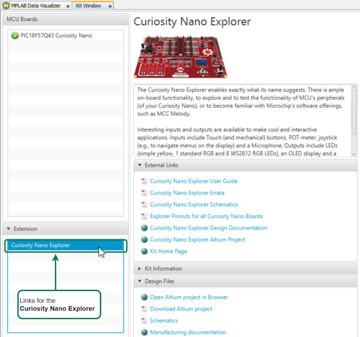
When plugging in a Curiosity Nano evaluation kit, MPLAB® X IDE will open the Kit Window tab, which contains a number of useful links for the particular board that you have.
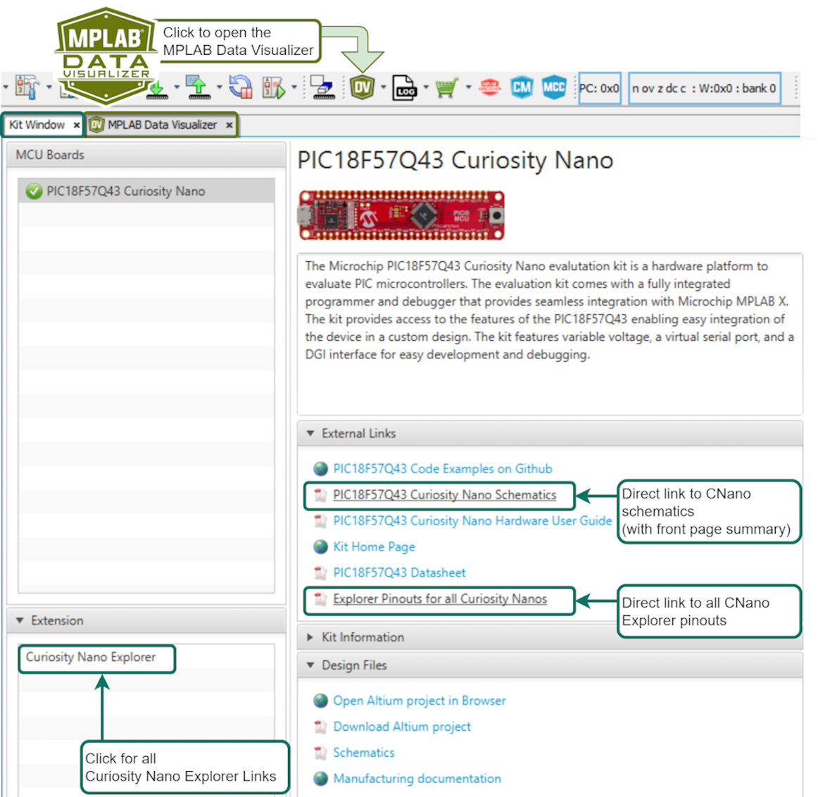
Click the Curiosity Nano Schematics link, as shown in the image above, to quickly find the UART connected to the USB CDC of the Curiosity Nano debugger. In addition, the user can quickly find the LED, Button and Debug GPIO pins.
2.4 Pins Selection: UART Tx/Rx
Once a UART Driver is added, your schematic must be referenced to select the right UART PLIB as a dependency. To do this, the schematics of your board must be referenced.
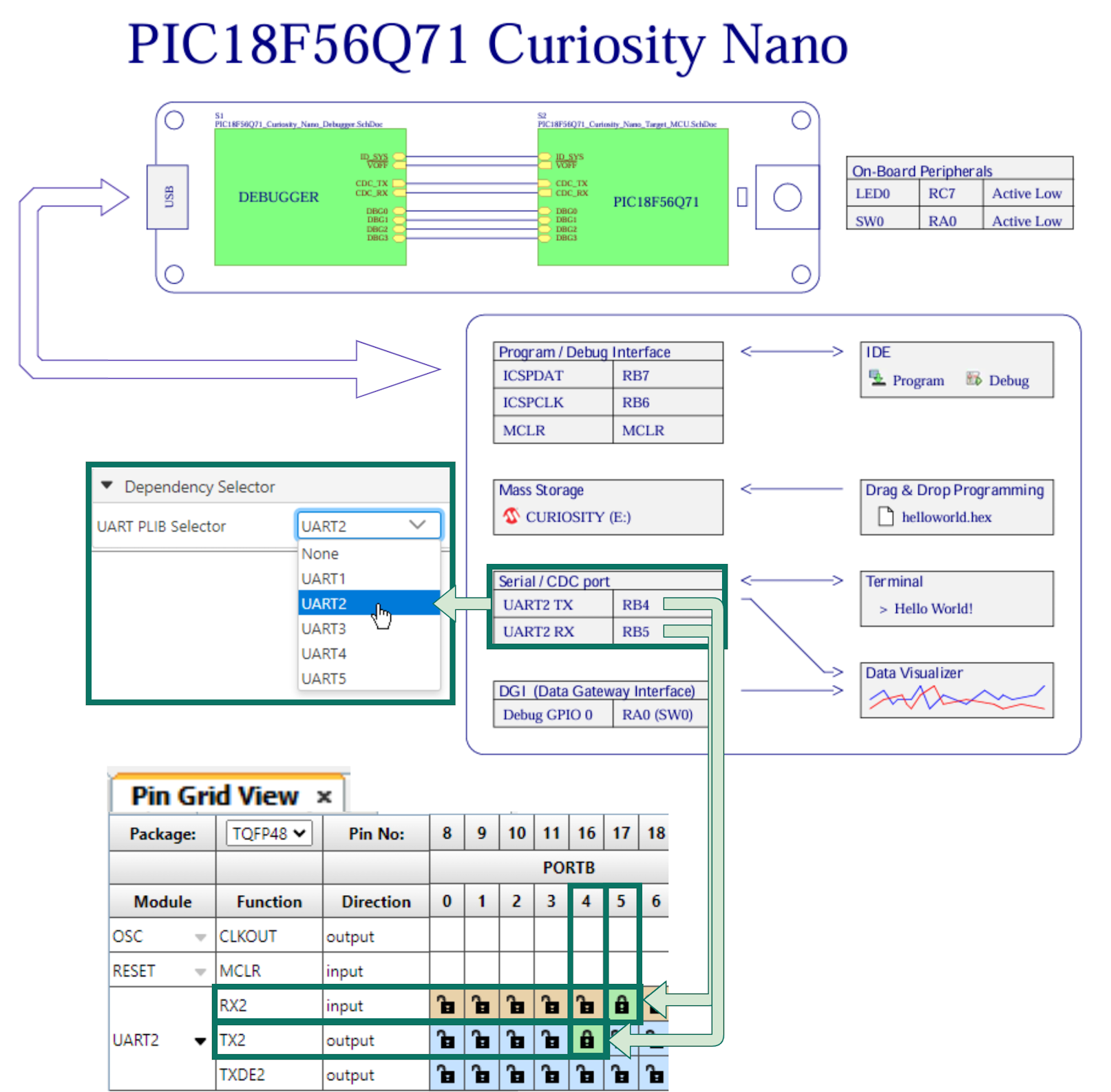
- The image above depicts an example for the Q71, where UART2 is connected to the Serial/CDC port, UART Tx is RB4 and Rx is RB5.
-
Different UARTs can be used for certain PIC MCUs due to Peripheral Pin Select (PPS). In this case, the specific pins used for UART Tx and UART Rx play a significant role.
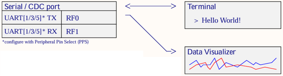
- It is possible to connect from the Serial/CDC port on the Curiosity Nano to either the Data Visualizer or a separate terminal program.
- For an introduction to the Data Visualizer, see Visual Debugging with MPLAB® Data Visualizer.
2.5 Pins Selection: LED, BUTTON and Debug GPIO
Many examples include General Purpose Input/Output (GPIO). Since the default naming convention for PINs in MCC Melody starts with IO_, all the I/O pins in examples follows this convention. For example, IO_LED or IO_BUTTON.
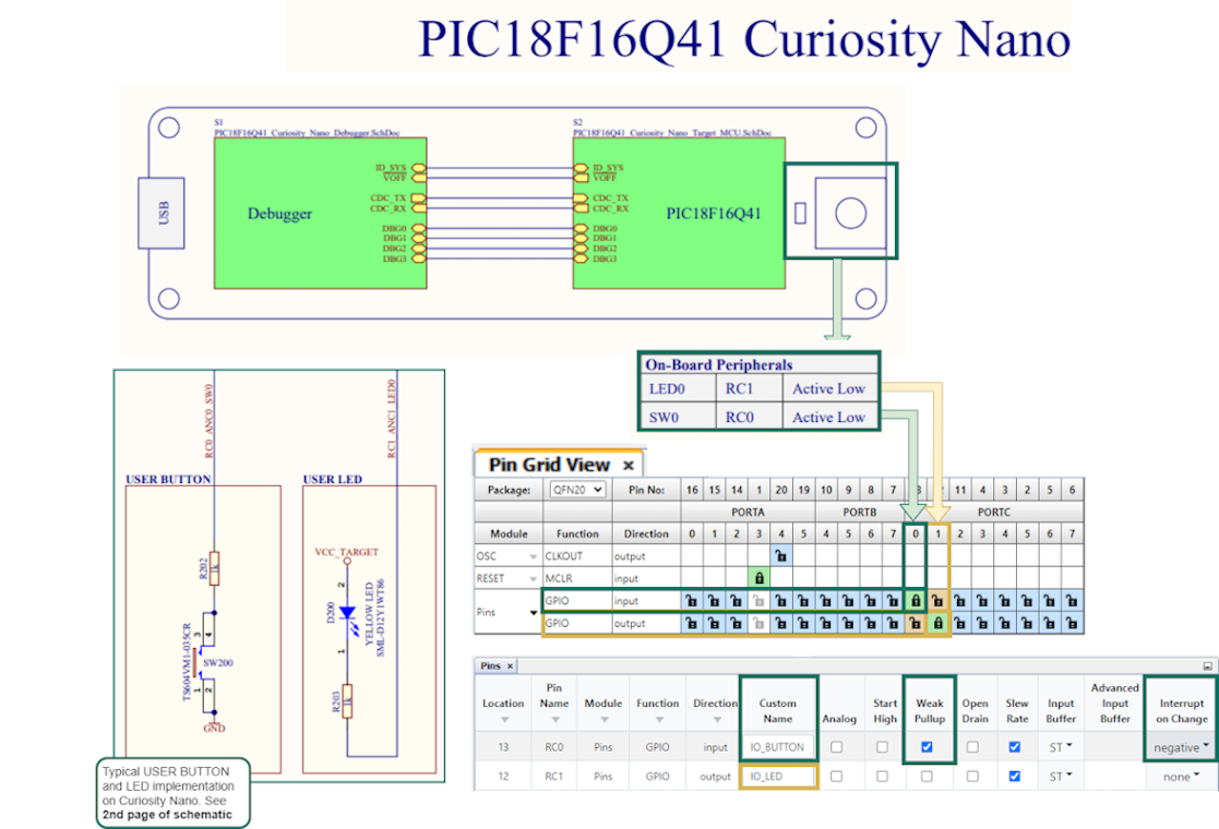
- Set the active low LED as output, rename to IO_LED.
- Set the active low BUTTON with no pull-up resistor as input, enable Weak Pull-up, set Interrupt-on-Change to Negative.
Debug GPIO pins are also provided on the Curiosity Nano via the Data Gateway Interface (DGI). Debug GPIO are particularly useful for a rough verification of application timing.
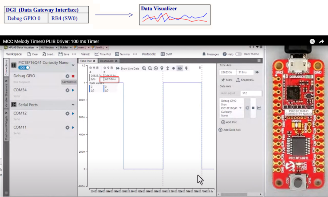
- Go to AVR TCA PLIB Driver, PIC Timer0 PLIB Driver for a video on how to use the MCC Melody 100 ms Timer.
- If you are new to MPLAB® Data Visualizer, see Debug GPIO Hello World (Microchip University).