
4 Getting Started PIC32CM MCU With VS Code and CMSIS Drivers
The following software and hardware tools are used for this demonstration:
- VS Code
- VS Code Plugins
- Arm CMSIS Solution
- Arm CMSIS Debugger
- Keil Studio Pack
- PIC32CM Curiosity Nano Evaluation Kit
CMSIS Environment Setup
Refer to this link for a step-by-step guide to installing CMSIS-Toolbox. Use a terminal window to run the commands below.
Follow the steps below to set up the environment for CMSIS based code generation:
- Install the
cmsis-toolboxbin folder to the system path under Environment Variables.wget https://artifacts.tools.arm.com/cmsis-toolbox/2.12.0/cmsis-toolbox-windows-amd64.zip -o cmsis-toolbox-windows-amd64.ziptar -xf cmsis-toolbox-windows-amd64.zip - To install the Device Family Pack
(DFP), run the command below on the terminal
window.
cpackget init https://artifacts.microchip.com/artifactory/pack-index/mdk/index.pidx - Verify that the installed DFP
pack is the latest public released version by running the
command.
cpackget add Microchip::PIC32CM-PL_DFP - For the Generic Software Pack
(GSP), initialize
cpackgetwith the Microchip pack index.cpackget init https://artifacts.microchip.com/artifactory/pack-index/mdk/index.pidx - Update to the latest Microchip
CMSIS Driver Pack using the command
below.
cpackget add Microchip::CMSIS-Driver_PIC32CM-PL - To apply the changes, restart the terminal window.
Creating the First Application on the PIC32CM MCU
To create a CMSIS based project, follow these steps:
- On the Start menu, launch VS Code.
- On the left navigation bar, click
the CMSIS plugin and select Create Solution.
Figure 4-1. Navigate to CMSIS and Solution Creation 
- Select the target board as PIC32CM6408PL10048 and press Select.
Figure 4-2. Device Selection 
- Select the Blank MCHP Driver
Solution template.
Figure 4-3. Template Selection 
- Select the project location and
click Create.
Figure 4-4. Project Location Selection 
- Under the Components tab, select
the GPIO and USART drivers from the CMSIS Driver drop-down. Select the dependent
plibs from the MCHP-PLIB drop-down option (PORT and SERCOM_USART1), along with
GCLK and MCLK, and click Save.
Figure 4-5. CMSIS Driver and MCHP PLIB Selection 
Adding Application Logic
To develop and run the application, use the following steps:
- Open the
main.cfile of the project and add the following application code.while (1) { /* -------- Switch Handling -------- */ curr_sw_state = GPIOdrv->GetInput(SW0); if ((prev_sw_state == 1) && (curr_sw_state == 0)) { blink_index = (blink_index + 1) % BLINK_TABLE_SIZE; blink_delay = blink_table[blink_index]; USARTdrv->Send(switch_msg, strlen((char *)switch_msg)); delay_ms(DEBOUNCE_TIME_MS); // Mechanical debounce } prev_sw_state = curr_sw_state; /* -------- LED Blink Timing -------- */ if ((g_ms_ticks - last_blink_time) >= blink_delay) { last_blink_time = g_ms_ticks; led_state ^= 1U; GPIOdrv->SetOutput(LED0, led_state); snprintf(speed_msg, sizeof(speed_msg),"Blink Speed: %u ms\r\n", blink_delay); USARTdrv->Send(speed_msg, strlen(speed_msg)); } } - Add peripheral initialization
function calls and variable declarations inside
main.c, before thewhile(1)loop./******** System Initialization ********/ configure_clock(); configure_systick(); /******** GPIO Configuration ********/ // LED Output GPIOdrv->Setup(LED0, NULL); GPIOdrv->SetDirection(LED0, ARM_GPIO_OUTPUT); GPIOdrv->SetOutputMode(LED0, ARM_GPIO_PUSH_PULL); // Switch Input (Active LOW) GPIOdrv->Setup(SW0, NULL); GPIOdrv->SetDirection(SW0, ARM_GPIO_INPUT); GPIOdrv->SetPullResistor(SW0, ARM_GPIO_PULL_UP); /******** Interrupt Enable ********/ __DMB(); __enable_irq(); NVIC_EnableIRQ(SERCOM1_IRQn); /******** USART Configuration ********/ PORT_SetPeripheralMuxing(PIN_PB00, PORT_PERIPHERAL_FUNC_D); // TX PORT_SetPeripheralMuxing(PIN_PB01, PORT_PERIPHERAL_FUNC_D); // RX USARTdrv->Initialize(NULL); USARTdrv->PowerControl(ARM_POWER_FULL); USARTdrv->Control( ARM_USART_MODE_ASYNCHRONOUS | ARM_USART_PARITY_NONE | ARM_USART_STOP_BITS_1 | ARM_USART_DATA_BITS_8, USART1_DEFAULT_BAUD_RATE); USARTdrv->Control(ARM_USART_CONTROL_TX, 1); /******** Application Variables ********/ uint8_t blink_index = 0; uint32_t blink_delay = blink_table[0]; uint8_t prev_sw_state = 1; uint8_t curr_sw_state; uint32_t led_state = 0; uint32_t last_blink_time = 0; - Add header files, hardware pin
definitions, global variables, macros, and driver declarations at the start of
the
code.
/******************************************************************************* * Includes ******************************************************************************/ #include "RTE_Components.h" #include CMSIS_device_header #include <stdio.h> #include <stdlib.h> #include <string.h> /******************************************************************************* * Hardware Pin Definitions ******************************************************************************/ #define LED0 PIN_PB02 // Status LED #define SW0 PIN_PB03 // User switch /******************************************************************************* * Application Configuration Macros ******************************************************************************/ #define DEBOUNCE_TIME_MS 20U #define BLINK_TABLE_SIZE 4U /******************************************************************************* * CMSIS Driver Declarations ******************************************************************************/ extern ARM_DRIVER_GPIO Driver_GPIO; static ARM_DRIVER_GPIO *GPIOdrv = &Driver_GPIO; extern ARM_DRIVER_USART Driver_USART1; static ARM_DRIVER_USART *USARTdrv = &Driver_USART1; /******************************************************************************* * Global Variables ******************************************************************************/ static const uint32_t blink_table[BLINK_TABLE_SIZE] = {500, 1000, 2000, 4000}; static uint8_t switch_msg[] = "Switch Press Detected\r\n"; static char speed_msg[50]; volatile uint32_t g_ms_ticks = 0; // System millisecond tick counter - Add function prototypes and handlers below the global
variables.
/******************************************************************************* * Function Prototypes ******************************************************************************/ void configure_clock(void); void configure_systick(void); void delay_ms(uint32_t ms); /******************************************************************************* * SysTick Interrupt Handler * Increments 1ms system tick counter ******************************************************************************/ void SysTick_Handler(void) { g_ms_ticks++; } - Add function definitions below main
function.
/*******************************************************************************
 * Clock Configuration
 ******************************************************************************/
void configure_clock(void)
{
    OSCCTRL_OSCHF_EnableAutotune();
    OSCCTRL_OSCHF_SetFrequency(OSCCTRL_OSCHF_FREQ_4M);

    // SERCOM1 clock routing
    GCLK_SetPeripheralChannelGenSrc(GCLK_PCHCCTRL_8, GCLK_GENERATOR_0);
    GCLK_EnablePeripheralChannel(GCLK_PCHCCTRL_8);

    MCLK_EnableAPBCClock(MCLK_APBC_SERCOM1);
}

/*******************************************************************************
 * SysTick Configuration (1ms time base)
 ******************************************************************************/
void configure_systick(void)
{
    uint32_t core_clock_hz = OSCCTRL_OSCHF_GetFrequency();

    SysTick->LOAD = (uint32_t)((core_clock_hz / 1000U) - 1U);
    SysTick->VAL  = 0;

    SysTick->CTRL = SysTick_CTRL_CLKSOURCE_Msk |
                    SysTick_CTRL_TICKINT_Msk |
                    SysTick_CTRL_ENABLE_Msk;
}

/*******************************************************************************
 * Blocking Delay Function
 * Used only for short debounce timing
 ******************************************************************************/
void delay_ms(uint32_t ms)
{
    uint32_t start = g_ms_ticks;

    while ((g_ms_ticks - start) < ms)
    {
        ;   // wait
    }
}
Building and Programming Application
To build and program the application, follow these steps:
- The PIC32CM Curiosity Nano
evaluation kit supports debugging using a debugger. Connect the USB Type-C cable
to power and debug the PIC32CM Curiosity Nano evaluation kit.
Figure 4-6. Hardware Setup 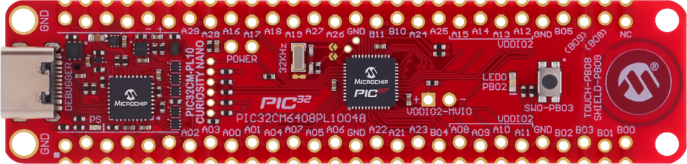
- Build the project by clicking the highlighted icon.
Figure 4-7. Build Solution 
- Program the application by clicking the highlighted icon.
Figure 4-8. Program Device 
Observing the Output on the Board and Serial Terminal
To observe the output on the board and serial terminal, follow these steps:
- Press the Start button to open any terminal window (TeraTerm in this case).
- Select the required serial port
and then click OK.
Figure 4-9. Selection of Serial COM Port 
- In the TeraTerm serial port setup
and connection dialog box, type or select 115200 as the baud rate in the Speed
box.
Figure 4-10. Setting the Baud Rate 
- An LED on the PIC32CM Curiosity Nano evaluation kit toggles on a timeout basis, with a default periodicity of 500 ms.
- The LED toggling rate is displayed on the Serial Terminal.
- Press the SW switch on the PIC32CM Curiosity Nano evaluation kit to change the default timeout periodicity to 1s.
- Each subsequent press of the SW
switch on the PIC32CM Curiosity Nano evaluation kit changes the timeout
periodicity to 2s, 4s, 500 ms, and back to 1s in a cyclic order.
Figure 4-11. Output Window 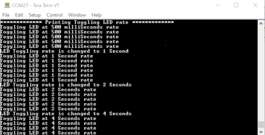
As the LED toggling rate displayed on the serial terminal changes with each subsequent switch press, observe the same change in the toggling rate of LED0 on the evaluation kit.