
5 Getting Started PIC32CM MCU With MPLAB X IDE
The following software and hardware tools are used for this demonstration:
- MPLAB X IDE v6.25 or newer
- MPLAB Code Configurator Plug-in v5.6.3 or newer
- MPLAB XC32 Compiler v5.00 or newer
- MPLAB Harmony v3 repository: csp v3.25 or newer
- MCC Core Version v5.8.3 or newer
- PIC32CM Curiosity Nano Evaluation Kit
Creating the First Application on the PIC32CM MCU
To create an MPLAB Harmony-based project, follow these steps:
- On the Start menu, launch MPLAB X IDE.
- On the File menu, click New Project or click the New Project icon.
- In the New Project window, on the left navigation bar, under Steps, click Choose Project.
Figure 5-1. Choose Project Window 
- In the Choose Project property page:
- Categories: Select Microchip Embedded.
- Project: Select Application Project(s).
- Click Next.
- In the left navigation bar, under Steps, click Select Device.
Figure 5-2. Device Selection Window 
- In the Select Device property page, type or select the device (e.g., PIC32CM6408PL10048) in the Device box.
- Click Next.
- In the left navigation bar, under Steps, click Select Compiler.
- In the Select Compiler property page, expand the XC32 list of options, and then select the compiler (e.g., XC32 (v5.00)).
Figure 5-3. Compiler Selection Window 
- Click Next.
- In the left navigation bar, click Select Project Name and Folder.
- In the Select Project Name and Folder property page:
- Project Name: Enter
getting_started_pic32cm_pl10_cnano. - Project Location: Click the Browse button and choose
C:\GettingStarted_With_PL10.
Figure 5-4. Project Name and Folder Selection Window 
- Project Name: Enter
- Click Finish.
- Before launching MCC, the Configuration Database Setup window will be displayed, where the Device Family Pack (DFP) and Cortex Microcontroller Software Interface Standard (CMSIS) path can be changed if required. For this demonstration, the default settings are used.
- The MCC plugin will open in a new window, as shown in the following figure.
Figure 5-5. MPLAB Code Configurator Window 
Adding and Configuring the MPLAB Harmony Component
To add and configure MPLAB Harmony components using MCC, follow these steps:
- In the MCC window, click Project Graph.
Figure 5-6. MPLAB Code Configurator 
- In the Plugins drop-down list, select Clock Configuration. The Clock Easy View window will be displayed, verify that the Main Clock is set to 24 MHz. Note: Ensure that the following modification is made for GCLK Generator 0.
Figure 5-7. MPLAB Code Configurator - GCLK Generator 0 
- Under Device Resources, expand the list of options: Harmony>Peripherals>SERCOM.
- Click SERCOM and observe that the SERCOM1 Peripheral Library block is added to the Project Graph window.
Figure 5-8. MPLAB Code Configurator - Selection of Peripheral  Note: Users can also select other peripherals under Device Resources: Harmony>Peripherals.
 - In the Project Graph window, on the left navigation bar, select the SERCOM1 Peripheral Library. In the Configuration Options property page on the right, configure it as follows to print data on the serial console at a baud rate of 115,200.
Figure 5-9. MPLAB Code Configurator – SERCOM1 Configuration 
- Under Device Resources, expand the list of options: Harmony>Peripherals>EIC. Click EIC and observe that the EIC Peripheral Library block is added to the Project Graph window.
- In the Project Graph window, on the left navigation bar, select the EIC Peripheral Library. In the Configuration Options property page on the right, select the Enable Interrupt checkbox and the Enable EIC Channel 3 checkbox for the switch press event.
Figure 5-10. MPLAB Code Configurator – EIC Configuration 
- Under Device Resources, expand the list of options: Harmony>Peripherals>RTC. Click RTC and observe that the RTC Peripheral Library block is added to the Project Graph window to generate a compare interrupt every 500 ms. Select the Clear on compare Match checkbox.Note: The compare value is set to 0x200. This value generates an RTC compare interrupt every 500 ms.
RTC Clock = 1024 Hz
RTC Prescaler = 1
Required Interrupt rate = 500 ms
Therefore, the compare value = (500/1000) x 1024 = 512 (i.e., 0x200).
Figure 5-11. MPLAB Code Configurator – RTC Configuration 
- From the Plugins drop-down list, select Add Channel and then select DMA Configuration. Configure DMA Channel 0 to transmit the application buffer to the USART TX register. The DMA transfers one byte from the user buffer to the USART transmit buffer on each trigger.
Figure 5-12. MPLAB Code Configurator – DMA Configuration 
- From the Plugins drop-down list, select Pin Configuration, and then click Pin Settings.
- In the Order box, type or select Ports. Build configurations according to the application as indicated below. Change the Custom Name of the pin IDs PB02 and PB03, as shown in the following figure.
Figure 5-13. MPLAB Code Configurator – Pin Configuration 
Code Generation
After configuring the peripherals as shown in the following figure, click Generate under Resource Management [MCC].

- The generated code will add files and folders to the 32-bit MCC Harmony project. In the generated code, notice the Peripheral Library files generated for the Real-Time Clock (RTC), External Interrupt Controller (EIC), PORT peripherals, SERCOM1 (as Universal Synchronous Asynchronous Receiver Transmitter (USART)), and the Direct Memory Access (DMA) peripherals. MCC also generates the
main.cfile. - MCC provides an option to change the generated file name. By default, the file name
main.cis used if a name is not assigned.
Adding Application Logic
To develop and run the application, follow these steps:
- Open the
main.cfile of the project and add the following application code.Figure 5-15. Logic for Register Callback Event Handlers 
- Implement the registered callback event handlers for the peripherals by adding the following code before the
main()function.static void SW_userHandler(uintptr_t context) { changeTempSamplingRate = true; } static void rtcEventHandler (RTC_TIMER32_INT_MASK intCause, uintptr_t context) { if (intCause & RTC_MODE0_INTENSET_CMP0_Msk) { isRTCExpired = true; } } static void uartDmaChannelHandler_Tx(DMAC_TRANSFER_EVENT event, uintptr_t contextHandle) { if (event == DMAC_TRANSFER_EVENT_COMPLETE) { isUARTTxComplete = true; } } - According to the status of the isRTCExpired and isUARTTxComplete flags (these flags are handled by the rtcEventHandler and uartDmaChannelHandler_Tx event handlers when the RTC timer expires and when UART completes the data transfer), LED0 is toggled at a default rate of 500 ms. To change the toggling rate, if the user presses the SW switch, the toggling rate changes to 1s, 2s, and 4s and then returns to 500 ms with subsequent switch press events. The SW_userHandler is responsible for changing the toggling rate when the user presses the SW switch on the board.
Inside the while loop, delete
SYS_Tasks()and add the following code to toggle the LED at a default rate of 500 ms.if ((isRTCExpired == true) && (true == isUARTTxComplete)) { isRTCExpired = false; isUARTTxComplete = false; LED_Toggle(); sprintf((char*)(uartTxBuffer), "Toggling LED at %s rate \r\n",&timeouts[(uint8_t)tempSampleRate][0]); DMAC_ChannelTransfer(DMAC_CHANNEL_0, uartTxBuffer,(const void *)& (SERCOM1_REGS->USART.SERCOM_DATA),strlen((const char*)uartTxBuffer)); } - Add the following code immediately after the code above to change the toggling rate when a switch press event occurs.
if(changeTempSamplingRate == true) { changeTempSamplingRate = false; if(tempSampleRate == TEMP_SAMPLING_RATE_500MS) { tempSampleRate = TEMP_SAMPLING_RATE_1S; RTC_Timer32CompareSet(PERIOD_1S); } else if(tempSampleRate == TEMP_SAMPLING_RATE_1S) { tempSampleRate = TEMP_SAMPLING_RATE_2S; RTC_Timer32CompareSet(PERIOD_2S); } else if(tempSampleRate == TEMP_SAMPLING_RATE_2S) { tempSampleRate = TEMP_SAMPLING_RATE_4S; RTC_Timer32CompareSet(PERIOD_4S); } else if(tempSampleRate == TEMP_SAMPLING_RATE_4S) { tempSampleRate = TEMP_SAMPLING_RATE_500MS; RTC_Timer32CompareSet(PERIOD_500MS); } else { ; } RTC_Timer32CounterSet(0); sprintf((char*)uartLocalTxBuffer, "LED Toggling rate is changed to %s\r\n", &timeouts[(uint8_t)tempSampleRate][0]); DMAC_ChannelTransfer(DMAC_CHANNEL_0, uartLocalTxBuffer, (const void *) &(SERCOM1_REGS->USART.SERCOM_DATA), strlen((const char*)uartLocalTxBuffer)); } - Add the following code to include the necessary header files and define the macros for different RTC compare values.
#include <stddef.h>                     // Defines NULL
#include <stdbool.h>                    // Defines true
#include <stdlib.h>                     // Defines EXIT_FAILURE
#include "definitions.h"                // SYS function prototypes
#include <string.h>
#include <stdio.h>
This code declares the various flags whose status is monitored and changed by the event handlers in the application. It also includes declarations and definitions of arrays used to print the LED toggling rate on the console.
static void SW_userHandler(uintptr_t context);
static void rtcEventHandler (RTC_TIMER32_INT_MASK intCause, uintptr_t context);
static void uartDmaChannelHandler_Tx(DMAC_TRANSFER_EVENT event, uintptr_t contextHandle);

/* Timer Counter Time period match values for input clock of 4096 Hz */
#define PERIOD_500MS        (512)
#define PERIOD_1S           (1024)
#define PERIOD_2S           (2048)
#define PERIOD_4S           (4096)

#define TX_BUFFER_SIZE      (100)

static volatile bool isRTCExpired = false;
static volatile bool changeTempSamplingRate = false;
static volatile bool isUARTTxComplete = true;
static volatile bool isUARTRxComplete = false;

static uint8_t uartTxBuffer[TX_BUFFER_SIZE] = {0};
Building and Programming Application
To build and program the application, follow these steps:
- The PIC32CM Curiosity Nano evaluation kit supports debugging using a debugger. Connect the USB Type-C® cable to the PIC32CM Curiosity Nano evaluation kit to power and debug the PIC32CM PL10 Curiosity Nano board.
- Ensure that the compiler optimization is set to 1. To check this, follow these steps:
- Right-click on the project
getting_started_pic32cm_pl10_cnano, a shortcut menu will appear. Click Properties.Figure 5-16. Project Properties 
- In the Project Properties window, under Option Categories, select Optimization, and from the optimization-level item list, select 1.
- Click OK to close the Project Properties window.
Figure 5-17. Compiler Optimization Level 
Figure 5-18. Hardware Setup 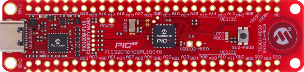
- Right-click on the project
- Set
getting_started_pic32cm_pl10_cnanoas the main project, and in Project Properties, select the latest compiler version (v5.00). Clean and build the project by clicking the highlighted icon.Figure 5-19. Clean and Build Main Project 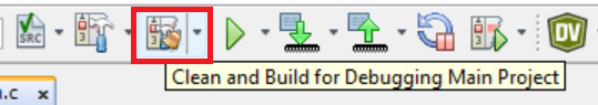
- Program the application by clicking the highlighted icon.
Figure 5-20. Make and Program Device 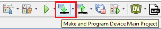
Observing the Output on the Board and Serial Terminal
To observe the output on the board and serial terminal, follow these steps:
- Open any terminal window (TeraTerm in this case).
- Select the required serial port and then click OK.
Figure 5-21. Selection of Serial COM Port 
- In the TeraTerm serial port setup and connection dialog box, type or select 115200 as the baud rate in the Speed box.
Figure 5-22. Setting the Baud Rate 
- An LED on the PIC32CM Curiosity Nano evaluation kit toggles on a timeout basis, with a default periodicity of 500 ms.
- The LED toggling rate is displayed on the serial terminal.
- Press the SW switch on the PIC32CM Curiosity Nano evaluation kit to change the default timeout periodicity to 1s.
- Each subsequent press of the SW switch on the PIC32CM Curiosity Nano evaluation kit changes the timeout periodicity to 2s, 4s, 500 ms, and back to 1s in cyclic order.
Figure 5-23. Output Window 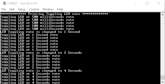
As the LED toggling rate displayed on the serial terminal changes with each subsequent switch press, observe the same change in the toggling rate of LED0 on the evaluation kit.