7.1.1 FFD Project Creation with MAC Component
Developing the Application from Scratch using MCC
- Create a new MCC Harmony Project. For more details, refer to the Creating a New MCC Harmony Project from Related Links.
- From the Device Resources tab, navigate to Harmony>Wireless>Drivers>IEEE 802.15.4>IEEE 802.15.4 MAC.
- Click the plus symbol (+) to add
the IEEE 802.15.4 MAC component (see the following figure).
Figure 7-1. FFD Project - IEEE 802.15.4 MAC Component  Note: The Device Resources tab displays IEEE 802.15.4 PHY and MAC components only if you clone the wireless_15_4_phy and wireless_15_4_mac repository in the MCC framework path.
 - Upon selection, the user receives a prompt for auto-activation and auto-connect request of different component dependencies. Click Yes to add all the dependent components and also for all attachment auto-connect requests.
- Right click the TIME
module for selecting the timer source.
- The user can select any of the timer source. For example, go to Available Satisfiers>TC0 (tc0).
Figure 7-2. FFD Project - Timer Component 
- Click the TIME Component.
Open Configuration Options tab and perform the following steps:
- Change the “Number of
Clients” 5 to 10 based on software timers.
Figure 7-3. FFD Project - Number of Clients 
- Change the “Number of
Clients” 5 to 10 based on software timers.
- Click the IEEE 802.15.4
MAC component. Open Configuration Options tab and perform the
following steps:
- In “Device Type
Configuration” field, select FFD from the drop-down list for FFD
project generation.Note: If security required, from “MAC Security Config” drop-down list, select Enabled.
Figure 7-4. FFD Project - IEEE 802.15.4 MAC Device Type Configuration 
- In “Device Type
Configuration” field, select FFD from the drop-down list for FFD
project generation.
- If console prints is required,
the user can add a “CONSOLE” component to facilitate application console
prints.
- In the Device Resources tab, navigate to Libraries>Harmony>System Services.
- Click the plus symbol (+) to add CONSOLE component (see the
following figure).
Figure 7-5. Adding CONSOLE Component 
- In the project graph,
right click on UART. Navigate to
UART>Satisfiers>SERCOM0 to add and connect
the SERCOM0 component.
Figure 7-6. SERCOM0 Console Component 
- Click on the
SERCOM0 component. Open Configuration Options tab and
perform the following steps:
- Change “TX Ring Buffer Size” and “RX Ring Buffer Size”.
- Change “Receive Pinout” and “Transmit Pinout”.
Figure 7-7. SERCOM0 Configurations 
- Configure the SERCOM0 to
enable the direct high speed by performing the following steps:
- In “Project Graph” window, click the System component to open Configuration Options tab.
- To locate “SERCOM0 Direct (High Speed) Pin Enable (SCOM0_HSEN)”, navigate to System>Device & Project Configuration>PIC32WM_BZ6204 Device Configuration>Generate Fuse Settings>DEVCFG1
- From “SERCOM0 Direct (High Speed) Pin Enable (SCOM0_HSEN)” drop-down list, select DIRECT.
Figure 7-8. System Configuration - SCOM0_HSEN Pin 
- In the Device Resources
tab, click the plus symbol (+) to add PIC32WM BZ6 Curiosity BSP.
Figure 7-9. Device Resources - Board Support Packages 
- The user can review the final project graph in the Project Graph window. The
following figure illustrates the MAC project graph.
Figure 7-10. MAC Project Graph (Full) 
- Click Generate to generate
code. The system adds the MAC files to the project upon code generation. For
more details on code generation, refer to the MPLAB Code Configurator (MCC)
Code Generation from Related Links.
Figure 7-11. Code Generation 
- After the completion of code
generation, the system adds the header, source, and library files of MAC to the
project under the
config/IEEE_802154_MACdirectory.Figure 7-12. Project Files 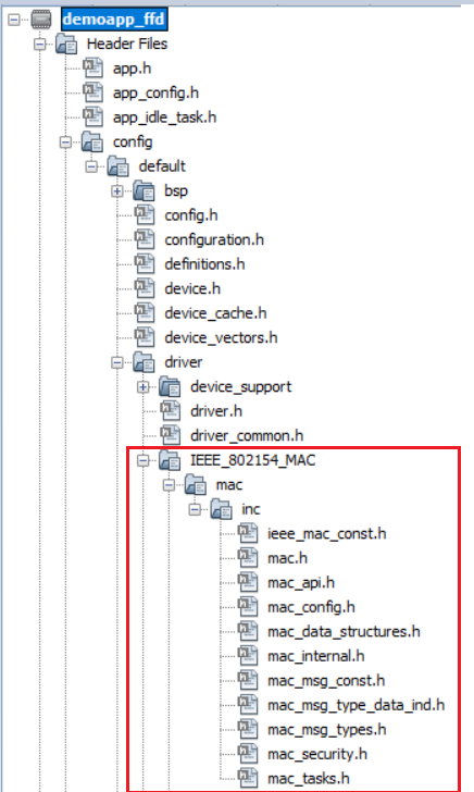
Figure 7-13. MAC Source Files 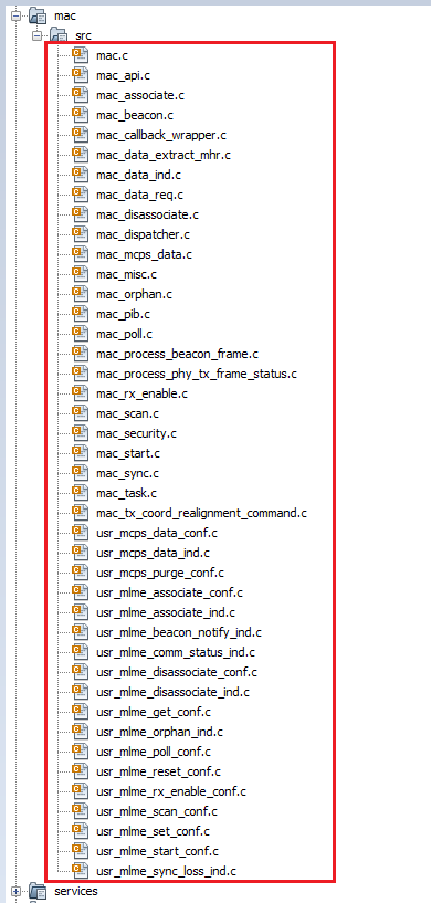
- The system creates an RTOS task for the MAC layer.
tasks.cfile andWPAN_Init ()will be called fromSYS_Initialize()function. Change argument ofSYS_Load_Cal ()functionWSS_ENABLE_NONEtoWSS_ENABLE_ZBininitialization.cfile.Figure 7-14. initialization.c
Adding Files To The Project
- Copy the
demo_app_ffdapplication folder from the(wireless_apps_pic32_bz6/ apps/ieee_802_15_4 /MAC/ push_pull_mac_app/demoapp_ffd/firmware/src/) into created project folder (../firmware/src/)project repository.Figure 7-15. Project Repository 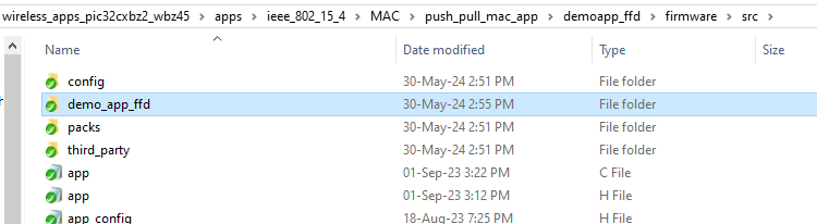
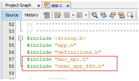
- Include the
demoapp_ffdfolder header files in project, as illustrated in the following figure.Figure 7-16. Header file 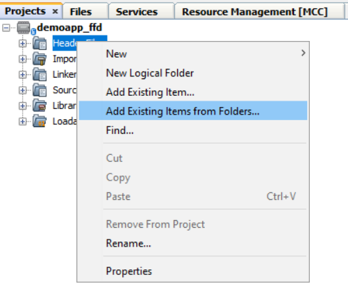
Figure 7-17. Including Header Files 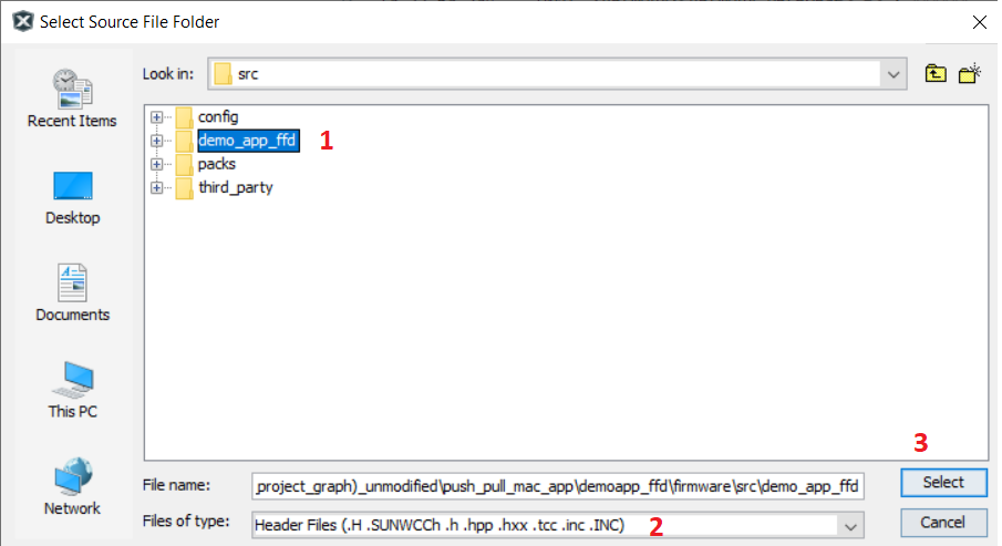
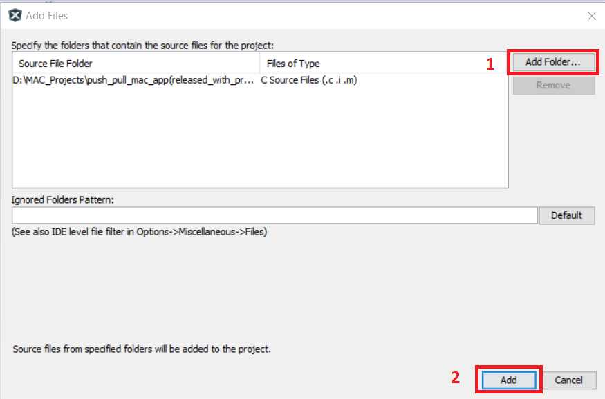
- After selecting the header files
from the demoapp ffd folder in current project folder. Click Add.
Figure 7-18. Add Files 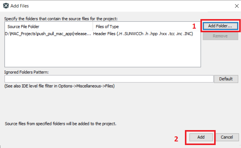
- Do the same steps to add the
source files to the project folder.
Figure 7-19. Source Files 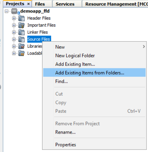
Figure 7-20. Including Source Files 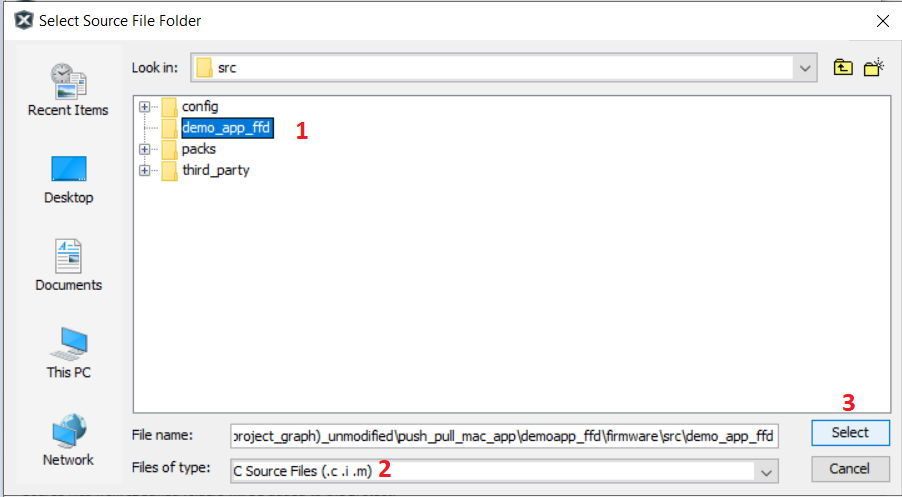
- After selecting the source files
from the demoapp ffd folder in current project folder. Click Add.
- Once the files are included the
project files will resemble as illustrated below.
Figure 7-21. Project Files 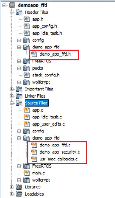
- Open Configuration for adding
include header files directories.
Figure 7-22. Set Configuration 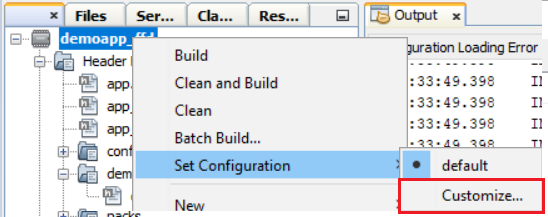
- In Project Properties,
- select XC32-gcc
- Select Preprocessing and messages in Option categories from the drop down
- Click Include directories
Figure 7-23. Project Properties 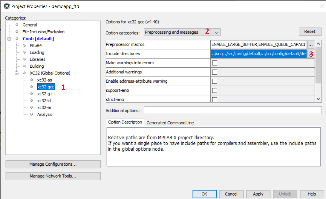
- Browse and include demoapp ffd
folder and click Apply and OK.
Figure 7-24. Include Directories 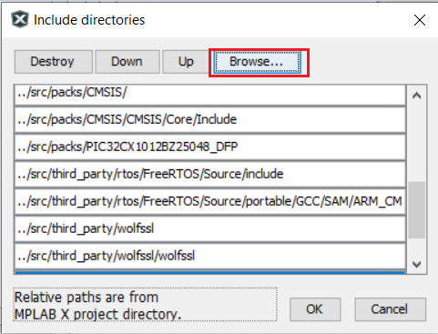
Figure 7-25. Including Files 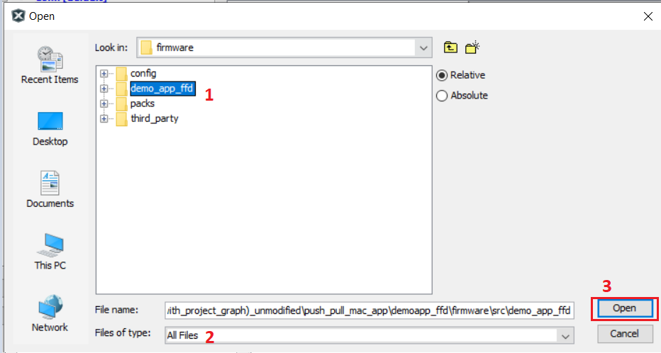
- app.h file changes: add FFD Demo
No beacon APP message ID’s.
Figure 7-26. app.h 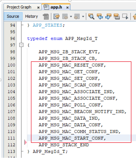
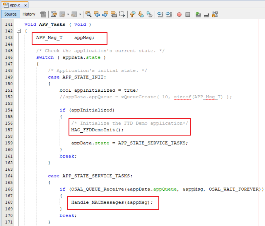
app.c file changes :
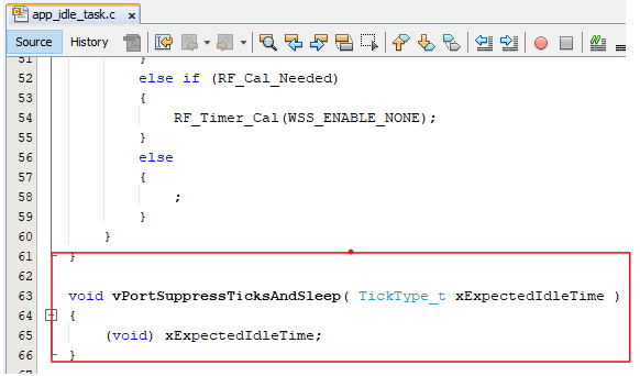
app_idle_task.c change:
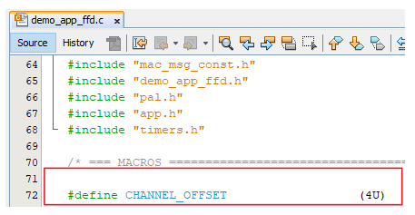
For channel configuration (example:CHANNEL_OFFSET :3 , Channel => 11 + 3 = 14)
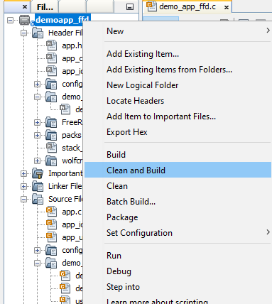
Right click on the project and Click on Clean and Build