
5 MPLAB® X Users Getting Started
MPLAB X with PIC18F56Q24 Curiosity Nano
Prerequisites
- MPLAB X installed
- The PIC18F56Q24 Curiosity Nano Board is connected to MPLAB X via the on-board USB connector connected to the embedded debugger. The USB powers the kit and the embedded debugger will enable debugging and programming via the USB.
- Microchip University Course: Introduction to MPLAB® X IDE
- Microchip University Course: Overview of the Microchip Code Configurator (MCC)
- Microchip University Course: MPLAB® Data Visualizer (for Curiosity Nano)
Workflow
- Launch MPLAB X.
- The page shown in the figure
below will appear when PIC18F56Q24 Curiosity Nano is connected to MPLAB X.
Figure 5-1. PIC18F56Q24 Curiosity Nano Page in MPLAB® X 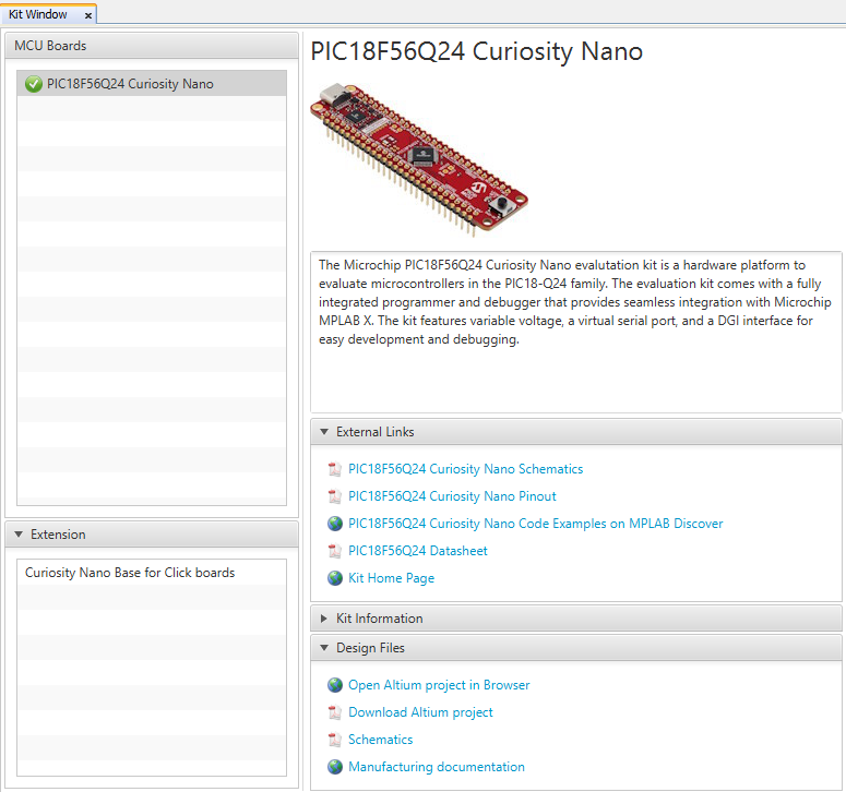
- Start creating a new project by
clicking File→New Project or using the <Ctrl+Shift+N>
shortcut, as shown in Figure 5-2.
Figure 5-2. Create New Project in MPLAB X IDE 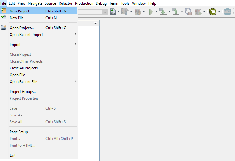
- Select the
Categories→Microchip Embedded and
Projects→Standalone Project template and click
Next.
Figure 5-3. New Project Window 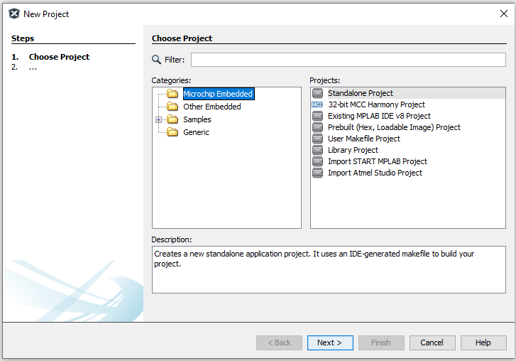
- Select PIC18F56Q24 and click
Next.
Figure 5-4. Device Selection Window 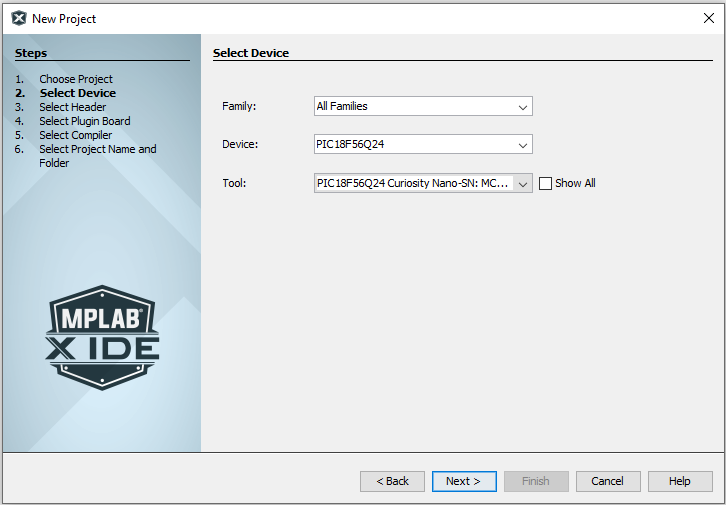
Then select the board and the desired compiler, if there are any.
- Select an available compiler
(e.g., XC8 (v.2.45)) and click Finish.
Figure 5-5. Compiler Selection Window 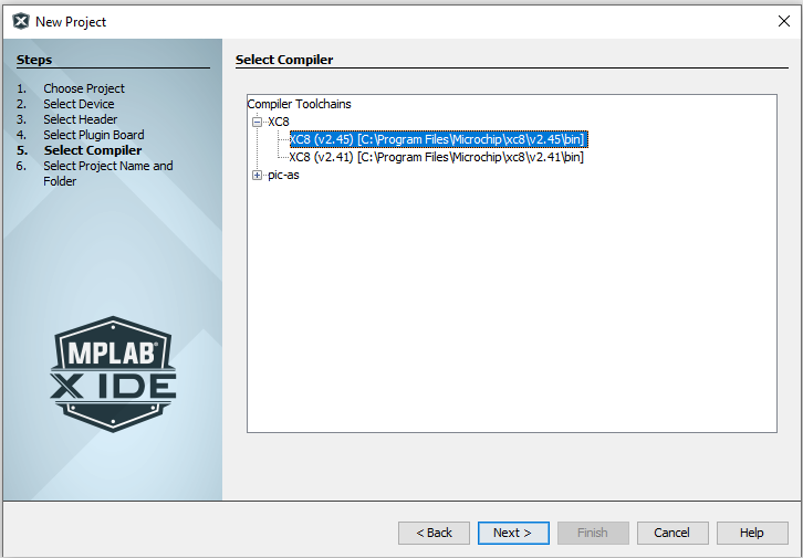
- Type in the name (e.g.,
LED_TOGGLE) and location (e.g.,
C:\) of the project and click Finish.Figure 5-6. Project Name and Location Selection Window 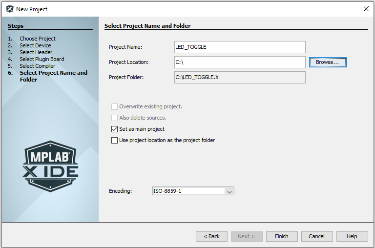
- Create a new
main.cfile by clicking File→New File or using the <Ctrl+N> shortcut.Figure 5-7. Create a New File in MPLAB X 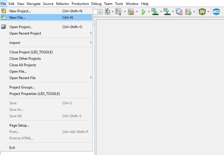
- Select the
Categories→C and File Types→C Main File
template, then click Next.
Figure 5-8. New File Window 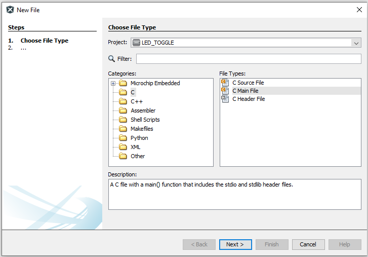
- Type in the file name (e.g.,
main) and click Finish.Figure 5-9. File Name Window 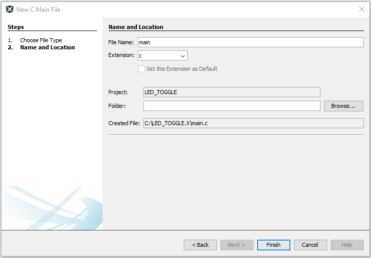
- Replace the
main.cfile with the following code snippet:#include <xc.h> int main(void) { PORTF = 0x00; /* Clear PORTA */ LATF = 0x00; /* Clear Data Latch */ ANSELF = 0x00; /* Enable digital drivers */ WPUF = 0x08; /* Enable weak pull-up for SW0 */ TRISF = 0x08; /* Configure SW0 (RF3) as input and LED0 (RF2) pin as output */ while (1) { /* Check the status of SW0 */ /* 0: Pressed */ if (PORTFbits.RF3 == 0) { LATFbits.LATF2 = 0; /* LED0 ON */ } else { LATFbits.LATF2 = 1; /* LED0 OFF */ } } return (EXIT_SUCCESS); }
Add
#include <xc.h>inmain.c. In the code editor, the code will appear as shown below.Figure 5-10. Code Editor Window 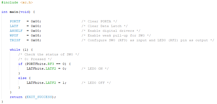
- Build the code by clicking Production→Clean and Build Main Project or using the <Shift+F11> shortcut.
- Program PIC18F56Q24 with the project code and start debugging by clicking Debug→Debugging Main Project.
- Steps 12 and 13 can be
accomplished in a single click by using the Debug Main Project option from the
toolbar.
Figure 5-11. Debug Main Project 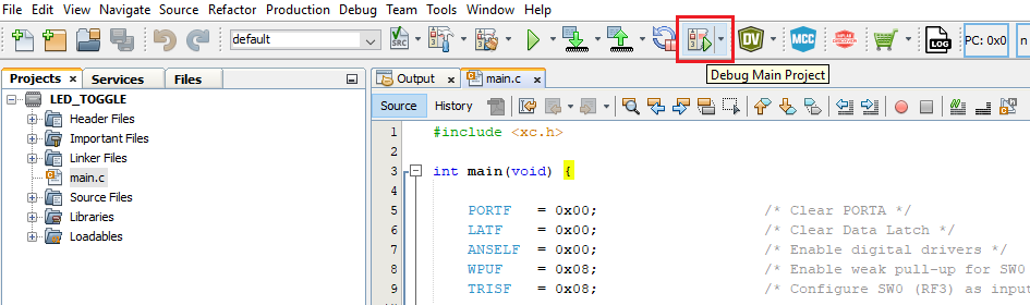
- Verify that LED0 is lit when SW0 is pushed on the PIC18F56Q24 Curiosity Nano.