5.8.1 Updating the Application Using a Bootloader Client With Secure Boot and Secure Device Firmware Update
This section demonstrates how to configure the application for a bootloader client with secure feature
footer_certificate.c file which needs to be updated with valid
addresses depending upon the application start address and size of the execution space. Description: This section details how to update the data in the
footer_certificate.c file and configure the linker settings of the
application project for multi-image support.
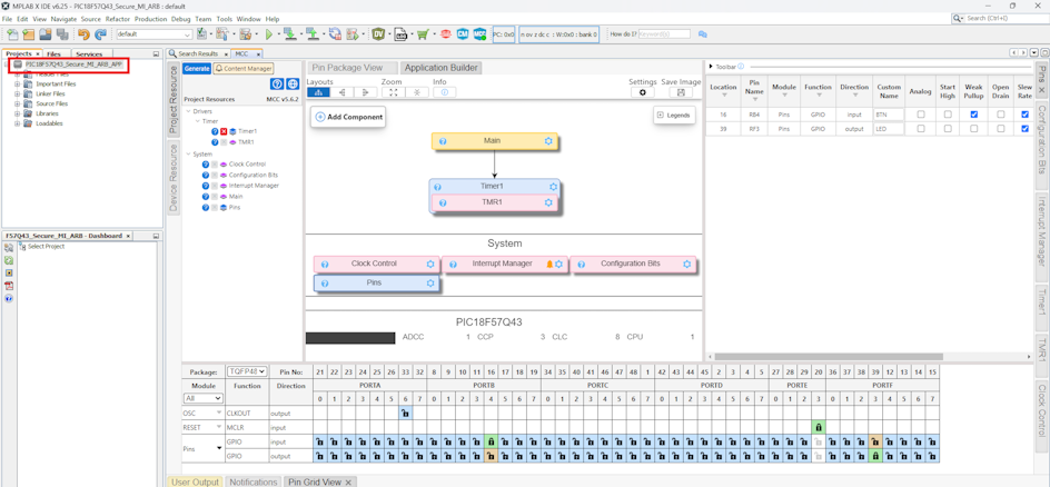
- Create a new MPLAB® X IDE project and
open MCC. MCC should open up automatically when a new project is created. If
not, click the MCC button in the menu bar to start the MPLAB Code
Configurator. For the configuration, select a timer, and enable the Interrupt
Driven toggle button and set the Requested Timer Period to 200 ms. In the
Configuration Manager, configure the setting for the IVTLOCK bit One-way set enable
bit to ‘IVTLOCKED bit can be cleared and set repeatedly’. In the Interrupt Manager,
the Enable Vectored Interrupt toggle button is enabled. IVT Base Address must be set
to 0x8008 (Application Address + Code Offset). Use the Pin Grid View to
select the GPIO pins for RB4 (renamed as BTN with Weak Pullup enabled) and RF3
(renamed as LED).
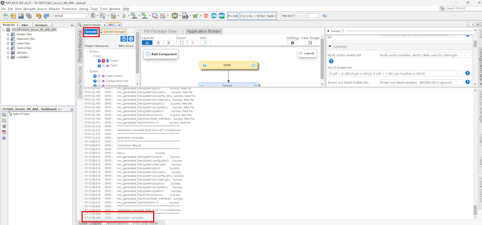
- Click on Generate.
Create and open the
footer_certificate.cfile.Note: The application builder automatically generates this file.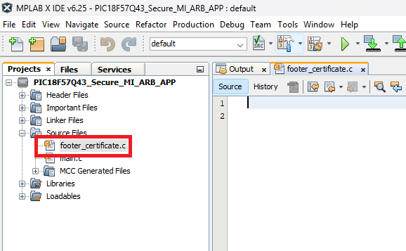
Add the following details into the file according to the configuration on the MDFU client UI.
Note: The execution space will always be 0x0000.
Understanding the variables stored in the footer data of the Flash memory:#define EXECUTION_SPACE (0x0000) #define STAGING_SPACE (0x0001) #define BACKUP_SPACE (0x0002) #include <stdint.h> #ifdef __XC8__ #include <xc.h> #endif volatile const uint16_t #ifdef __XC8__ __at(0xFFAE) #endif applicationSlotId __attribute__((used, section("application_slot_id"))) = EXECUTION_SPACE; volatile const uint32_t #ifdef __XC8__ __at(0xFFB0) #endif applicationVersion __attribute__((used, section("application_version"))) = 0x00000100; volatile const uint32_t #ifdef __XC8__ __at(0xFFB4) #endif verificationEndAddress __attribute__((used, section("application_verify_end"))) = 0x0000FFBBU; volatile const uint32_t #ifdef __XC8__ __at(0xFFB8) #endif verificationStartAddress __attribute__((used, section("application_verify_start"))) = 0x00008000U; volatile const uint32_t #ifdef __XC8__ __at(0xFFBC) #endif footerSignature[] __attribute__((used, section("atecc608_certificate"))) = { 0, 0, 0, 0, 0, 0, 0, 0, 0, 0, 0, 0, 0, 0, 0, 0 }; volatile const uint32_t #ifdef __XC8__ __at(0xFFFC) #endif applicationHash __attribute__((used, section("application_hash"))) = 0xFFFFFFFFU;Table 5-4. Footer Certificate Data Variable Purpose Address applicationSlotId This is the location where the current image will be stored. Current Example Value: EXECUTION_IMAGE_ID
Should be: Image ID of the image location to update
The address in the __at()is calculated by subtracting two from the start address of the applicationVersion.The two bytes are used for storing the uint16_t type variable applicationId.
This value might change for your application.
applicationVersion This is the version of the current application. Current Example Value: 0x00000100
Should be: Version of the application
Warning: Application version cannot be 0 or 4294967295 (0xFFFFFFFF).The address in the __at()is calculated by subtracting four from the start address of the verificationEndAddress.The four bytes are used for storing the uint32_t type variable applicationVersion.
If rollback protection is enabled, this value must be updated whenever a new application image needs to be loaded.
verificationEndAddress This is the last address that is considered for the hash calculation mapped into the execution space. The value of this argument must always fall within the execution space.
Current Example Value: 0x0000FFBBU
Should be: Execution Image End Address
The address in the __at()is calculated by subtracting four from the start address of the verificationStartAddress.The four bytes are used for storing the uint32_t type variable verificationEndAddress.
This value might change for your application.
verificationStartAddress This is the first address that is considered for the hash calculation mapped into the execution space. The value of this argument must always fall within the execution space.
Current Example Value: 0x00008000U
Should be: Execution Image Start Address
The address in the __at()is calculated by subtracting four from the footer signature address.The four bytes are used for storing the uint32_t type variable verificationStartAddress.
This value might change for your application.
footerSignature[] This variable will hold the cryptographic signature appended to the end of the firmware image used by the secure bootloader to verify the integrity and authenticity of the image before execution The address in the __at()is calculated by subtracting sixty four from the start address of the application hash address.The sixty four bytes are used for storing the uint32_t type array 16 spaces array of the footer signature.
This value might change for your application.
applicationHash This variable holds the cryptographic hash of the application image The address in the __at()is calculated by subtracting four from the end address of the application image to be verified.The four bytes are used for storing the uint32_t type variable applicationHash.
This value might change for your application.
- Add the following code into the
main.cfile.For PIC devices:
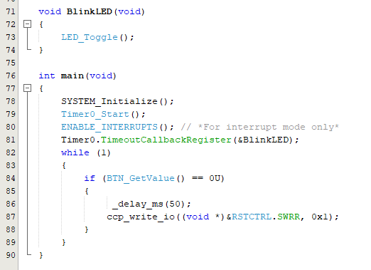
#include "mcc_generated_files/system/system.h"
#include "mcc_generated_files/timer/tmr0.h"
/*
    Main application
*/
void BlinkLED(void)
{
    LED_Toggle();
}
int main(void)
{
    SYSTEM_Initialize();
    // If using interrupts in PIC18 High/Low Priority mode, enable the Global High and Low Interrupts
    // If using interrupts in PIC Mid-Range Compatibility mode, enable the Global Interrupts
    // Use the following macros to:

    // Enable the Global High Interrupts
    INTERRUPT_GlobalInterruptHighEnable();

    // Disable the Global High Interrupts
    //INTERRUPT_GlobalInterruptHighDisable();

    // Enable the Global Low Interrupts
    INTERRUPT_GlobalInterruptLowEnable();

    // Disable the Global Low Interrupts
    //INTERRUPT_GlobalInterruptLowDisable();

    Timer0.TimeoutCallbackRegister(&BlinkLED);

    while (1)
    {
        if (BTN_GetValue() == 0U)
        {
            RESET();
        }
    }
}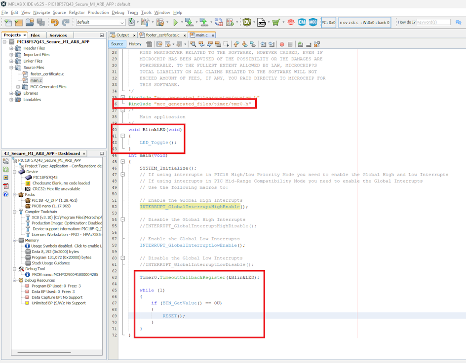
For AVR devices:
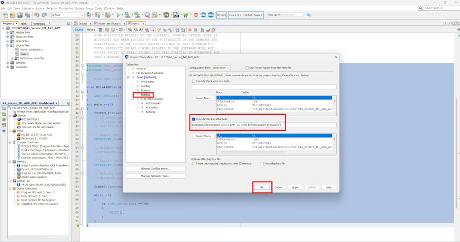
- In Project Properties, set the
Building > Execute this line after build with the following
configuration:
- Additionally, the linker settings
need to be updated to restrict the ROM range to the current application image ID’s
Flash range.
- For PIC devices: Where 8000-FFFF is
Figure 5-202. Compiler - Linker Settings 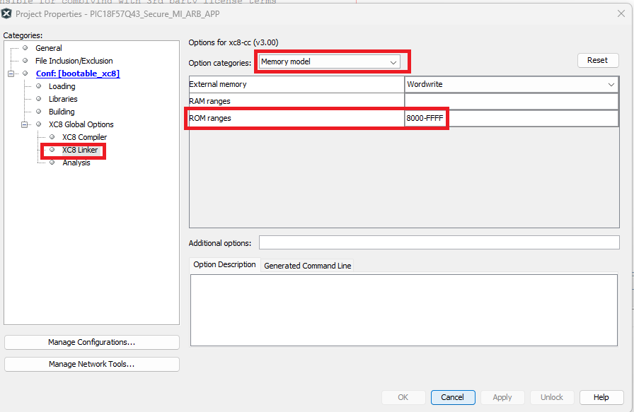
<applicationId image start address:
                            applicationId image end address>
. These values can be updated by referring to the Device Flash Memory Partitions Table in the MDFU Client UI and the applicationId. - For AVR devices:
For an AVR-based bootloader client with applicationId image range of 0x8000-0xFFFF the linker settings are as follows:
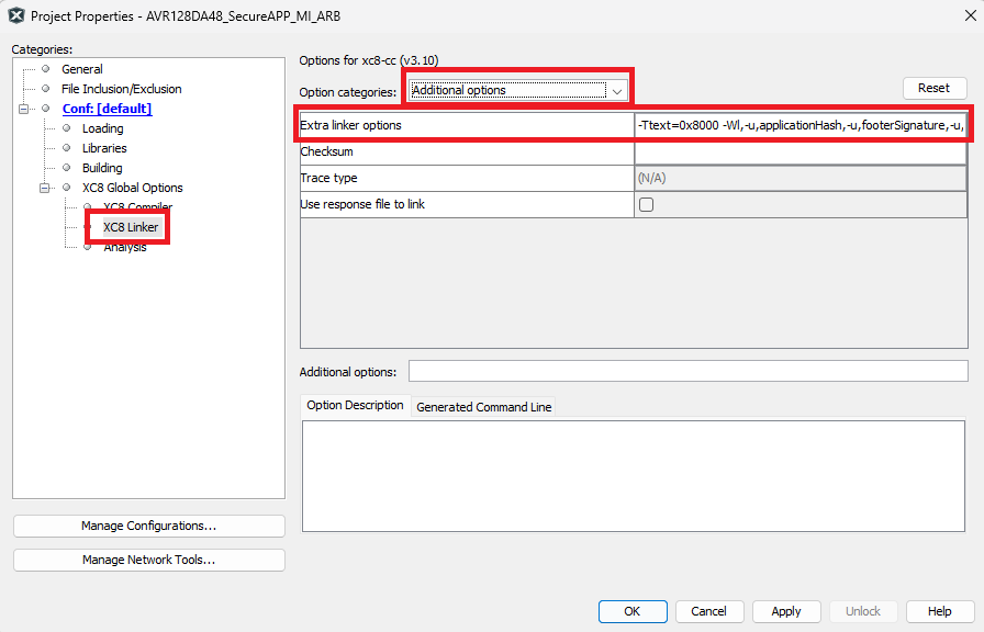
- XC8 linker
settings:
Open Project Properties>XC8 Linker>Additional Options. In the “Additional Options” text box, add
-Wl,-u,checksumStart,-u,verificationStartAddress,-u,verificationEndAddress,-u,applicationVersion,-u,applicationId,-u,__TEXT_REGION_LENGTH__=<applicationId image start address: applicationId image end address>,-Ttext=<applicationId image start>XC8 Linker Settings
- GCC Linker
SettingsOpen Project Properties>Avr GCC (Global Options)>avr-ld>General. In the “Additional Options” text box, add
-Wl,-u,checksumStart,-u,verificationStartAddress,-u,verificationEndAddress,-u,applicationVersion,-u,applicationId,-u,__TEXT_REGION_LENGTH__=<applicationId image start address: applicationId image end address>,-Ttext=<applicationId image start>Figure 5-203. GCC Linker Settings 
- XC8 linker
settings:
- For PIC devices:
- Create a new file under Important
Files section by right clicking and going to Important Files>New>Empty
File. Name the file as postBuildSigning.bat and add the following content.
@echo off REM This post-build script performs a sequence of operations to prepare, sign, and manage firmware images for secure application deployment. REM This script uses OpenSSL for two main operations: REM 1. Digital Signature Creation REM 2. Verification with public key (Optional: Useful while testing with new keys) REM This script also uses the pyasn1 python library to convert the signature from DER format to a raw binary format. REM _________________________________________________________________________________________________________________________________________________________________________________________________________________________ REM Blank signature location - This step inserts 0x00s to the Flash memory locations where signature is stored REM Generic command description: REM if %1==CRC32/16 hexmate r<verificationStartAdress>-<flash end address>,%4\%3.X.production.hex -O%4\temp_original_copy.X.production.hex -FILL=w1:0x00,0x00@<SignatureStartAddress>:<execution space end address> if %1==CRC32 hexmate r8000-1FFFF,%4\%3.X.production.hex -O%4\temp_original_copy.X.production.hex -FILL=w1:0x00,0x00@0xFFBC:0xFFFF REM Fill in unimplemented Flash locations - Filling the unimplemented Flash locations in application range REM Generic command description: REM hexmate r0-FFFFFFFF,%4\temp_original_copy.X.production.hex -O%4\temp_original_copy.X.production.hex -FILL=w1:0xFF@verificationStartAdress>:<execution space end address> hexmate r0-FFFFFFFF,%4\temp_original_copy.X.production.hex -O%4\temp_original_copy.X.production.hex -FILL=w1:0xFF@0x8000:0xFFFF REM Generate application binary image - Shifts the hex data back by <verificationStartAddress> bytes and converts the hex file into a binary file REM Generic command description: REM if %1==CRC32 hexmate r<verificationStartAddress>-<verificationEndAddress>s-<verificationStartAddress>,%4\temp_original_copy.X.production.hex -O%4\temp_original_copy.X.production.hex if %1==CRC32 hexmate r8000-FFBBs-8000,%4\temp_original_copy.X.production.hex -O%4\temp_original_copy.X.production.hex REM This command converts the shifted hex into a binary file %2\avr-objcopy -I ihex -O binary %4\temp_original_copy.X.production.hex %4\%3.X.production.bin REM Sign binary with the correct private key openssl dgst -sha256 -sign .\sjcl_random_private_key_2.pem %4\%3.X.production.bin > %4\%3.X.production.bin.signature.der REM Verify using OpenSSL openssl dgst -sha256 -verify "public_key.pem" -signature %4\%3.X.production.bin.signature.der %4\%3.X.production.bin REM Export signature value python "signature_der_to_bin.py" %4\%3.X.production.bin.signature.der %4\%3.X.production.bin.signature.bin REM This command converts the signature binary into a hex file %2\avr-objcopy -I binary -O ihex %4\%3.X.production.bin.signature.bin %4\%3.X.production.bin.signature.hex REM Copy signature .hex into application .hex file application header REM LOGIC: Signature hex (shifted to signature start address) + existing application hex + existing application hex 2 (verification data - CRC32) ==> new application hex REM Generic command description: REM if %1==CRC32 hexmate r0-3Fs<verification End Address + 1>,%4\%3.X.production.bin.signature.hex r0-FFBB,%4\%3.X.production.hex r<application Hash address>-FFFFFFFF,%4\%3.X.production.hex -O%4\%3.X.production.hex if %1==CRC32 hexmate r0-3FsFFBC,%4\%3.X.production.bin.signature.hex r0-FFBB,%4\%3.X.production.hex rFFFC-FFFFFFFF,%4\%3.X.production.hex -O%4\%3.X.production.hex REM Fill unimplemented Flash locations in the hex generated above including CRC location REM Generic command description: REM if %1==CRC32 hexmate r0-FFFFFFFF,%4\%3.X.production.hex -O%4\%3.X.production.hex -FILL=w1:0xFF@0x<verification start Address>:<execution space end address> if %1==CRC32 hexmate r0-FFFFFFFF,%4\%3.X.production.hex -O%4\%3.X.production.hex -FILL=w1:0xFF@0x8000:0xFFFF REM Delete the temporary files del %4\%3.X.production.bin.signature.hex del %4\%3.X.production.bin.signature.bin del %4\%3.X.production.bin.signature.der del %4\temp_original_copy.X.production.hex del %4\%3.X.production.bin - Create a
signature_der_to_bin.pyfile with the following content.from pyasn1.codec.der import decoder from pyasn1.type.univ import Sequence import sys def der_to_bin(der_path, bin_path, curve_bytes=32): with open(der_path, 'rb') as der_file: der_data = der_file.read() sig_seq, _ = decoder.decode(der_data, asn1Spec=Sequence()) # Get r and s integers r = int(sig_seq[0]) s = int(sig_seq[1]) # Convert to bytes, pad to proper length r_bytes = r.to_bytes(curve_bytes, byteorder="big") s_bytes = s.to_bytes(curve_bytes, byteorder="big") with open(bin_path, 'wb') as bin_file: bin_file.write(r_bytes + s_bytes) print(f"Converted {der_path} -> {bin_path}") if __name__ == "__main__": if len(sys.argv) < 3: print("Usage: python signature_der_to_bin.py signature.der signature.bin [curve_bytes=32]") sys.exit(1) der_path = sys.argv[1] bin_path = sys.argv[2] curve_bytes = int(sys.argv[3]) if len(sys.argv) > 3 else 32 der_to_bin(der_path, bin_path, curve_bytes) - Add the required files for the keys
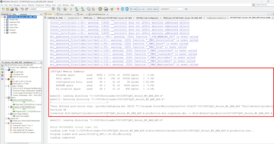
sjcl_random_private_key_2.pemandpublic_key.pem. This can be user generated or follow the Provisioning Guide which explains how to create these keys using OpenSSL®. - Click Clean and Build to the generate the project hex file.
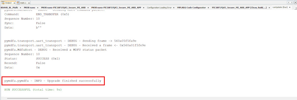
- Create the application image using the pyfwimagebuilder tool guide. The newly-generated application image can
be transferred to the target device using the Microchip Device Firmware Update
(pymdfu) tool.
Command:
pymdfu update --tool serial --image output.img --baudrate 115200 --port <COM PORT name>The update will run and finished successfully.