
2.5 Operating Principles of the LED Driver
The LED Driver implementation is fully firmware-based and uses various peripherals of the SAM R21 MCU to drive the LEDs.
Figure 2-4 shows the block diagram of the scheme used in the implementation of buck LED driver.
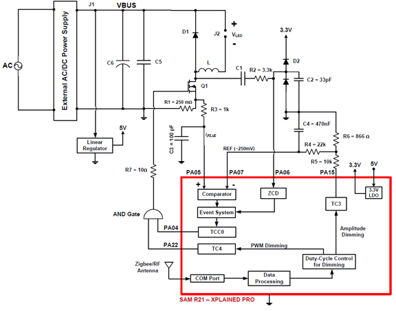
The SAMR21 controls the LED peak current using boundary-conduction-mode. The peripherals used for the implementation are:
- One Analog Comparator to monitor inductor or MOSFET peak current
- One Timer (TC3) for reference voltage generation for the inductor peak current for Amplitude Dimming
- One Timer (TC4) for PWM Dimming
- One PWM Timer (TCC0) for MOSFET control
- One external interrupt input channel for inductor Zero-Current-Detection (ZCD)
- Event system
The event system connects the output of the analog comparator and external interrupt (ZCD). It sends a signal to the timer TCC0 to start or stop the PWM signal for the buck MOSFET depending on the mode-of-transition (high-to-low or low-to-high) of analog comparator output and ZCD signals.
The reference for the peak current is generated using timer TC3. Timer TC3 generates a PWM signal at 10kHz with a desired duty-cycle and the PWM signal is passsed through a low-pass filter to give a DC reference for the analog comparator. The duty-cycle of TC3 is varied to adjust the reference voltage to achieve amplitude dimming.
The LED Driver implementation is available in
\Light\src\LightPwm.c
and corresponding header file.