3.3 Sine Wave Generation by Implementing Trigonometric Expressions
Sine wave and cosine wave are represented as shown in Figure 1.
Where,
V(t) = Instantaneous value
t = Time instant
F = Signal frequency
2π = Used for converting to radians
The trigonometric value of the radian angle is the instantaneous value of signal. The only difference between sine and cosine wave is the phase difference of 90°. Therefore, the instantaneous values of one wave can be obtained by phase shifting that of another wave by 90°. These waves are generated in the analog domain through oscillators. The basic wave equation, when converted to digital signal, can be represented as shown in Figure 2.
Where,
n = Instantaneous digital sample time which is an integer (I.e, 0, 1, 2, 3, 4, …, n)
T = Period/time between two samples of the wave
F = Signal frequency
Also,
Where,
f = F/Fs = Digital frequency from range -1/2 to 1/2
Fs = 1/T or T = 1/Fs (Fs = Sampling frequency)
In a digital computer, Equation 3-2 can be evaluated to generate samples of a specific frequency signal. The sine wave can be constructed using the Interpolation method or DAC. The digital frequency (f) can be calculated using F/Fs.
For example, if signal frequency = 1000 Hz, sampling frequency = 360000 Hz, then the value of f is shown in Equation 3-3.
Substituting the value of f in Figure 2 and incrementing the value of n from 0 to ∞, the sample values for cosine wave can be calculated. However, every calculation involves the evaluation of cosine of radian angle, which is the evaluation of cosine infinite series. The problem with this approach is that it consumes a higher number of CPU cycles. To overcome this problem, trigonometric analysis can be used to reduce the evaluation of infinite series to few floating point calculations. The standard trigonometric expressions are provided in Figure 4 and Figure 5.
Where,
= Sine of signal frequency present sample
= Sine of sampling frequency
= Cosine of signal frequency present sample
= Cosine of sampling frequency
= Cosine of signal frequency next sample
Where,
= Cosine of signal frequency previous sample
Figure 6 is derived by adding Equation 3-4 and Figure 5.
Figure 6 is rearranged as shown in Figure 7.
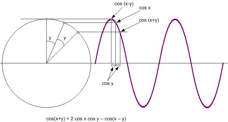
Consider Figure 8 for the angular representation of a sinusoidal waveform. Figure 8 can be used to calculate the next cosine value of cosine wave, if the previous and current samples of the signal and the cosine of sampling frequency is also known.
Where,
F = Signal frequency in Hz
Fs = Sampling frequency in Hz
f = F/Fs = Digital frequency from -0.5 to 0.5
y = Angular distance between the two points on the circle in radians (sampling rate in terms of angle in radians)
Figure 9 illustrates the trigonometric expressions provided in Figure 4 through Figure 8.

Figure 8 can be rewritten as shown in Figure 10.
Where,
y(n) = nthsample being calculated
y(n-1) = n-1stsample
y(n-2) = n-2ndsmaple
The first two samples of the cosine wave can be calculated by evaluating cos(2πf0) and cos(2πf1) directly.
-
cos(2πf1) is the cosine of the first sample which represents the angular distance between the 0th and first sample. Hence, it represents the angular distance covered during one sampling period on the signal.
-
Consider a circle of radius (r). Dividing the circle into Fs/F equal parts, the angle between two successive radius lines is the sampling rate. Hence, the cosine of that angle is the sampling frequency, which is in 2πfn radian, for n = 1. This is also the second sample of the signal where, n = 1 and y(n-1) = cos y = cos x.
The 8-bit MCUs do not contain floating point processor to perform the cosine infinite series evaluation, but the basic floating point operations such as addition, subtraction, multiplication and division can be emulated in software.
The recursive Figure 8 can be used to calculate the frequency signal samples for any sampling frequency. Also, the sine and cosine waves are periodic in nature and hence, only a single cycle needs to be calculated. The sample values repeat themselves after one cycle, hence no further calculations are needed. This will reduce the number of CPU cycles. A circular buffer can be used for easier implementation.
To convert the sample values into sine wave, at least 10 samples per cycle are required to reconstruct the signal shape. Hence, it is recommended to choose a sampling frequency that is ten times higher than the highest signal frequency. If the maximum signal frequency is 4000 Hz, the sampling rate should be 40000 Hz to keep the signal shape intact while reconstructing the sine wave.
The calculated sample values are in floating point format which need to be converted to integer format before sending them as input to the DAC, to create the analog signal. The resolution of the signal should be as high as possible (i.e, a signal with 10-bit sample values contains more fidelity in shape in reconstruction compared to a signal with 8-bit sample values).
Consider γ as the bit resolution for DAC. Multiplying the floating point sample values with (2γ–2(γ-1)) and adding 2(γ-1) to all the sample values will convert from (-1, 1) range to (0, 2γ), and rounding of the result will make an integer array of signal samples for one cycle as shown in Figure 11.
In 8-bit MCUs, the DAC with high resolution is rare, but there are Capture Compare (CCP) modules with PWM mode which can be used to convert the digital values to analog signal with a minimum resolution of 10 bits.
Initially, the PWM should be configured at 50% duty cycle. The PWM frequency should be the sampling frequency of the signal. For example, for a signal of 1000 Hz frequency sampled at 40000 Hz, the PWM frequency should be 40000 Hz at 50% duty cycle since every cycle or period of PWM signal should contain only one sample value of signal. If the two PWM periods contain the same sample value, filtering of the PWM will generate a stepped sine wave signal. The shape will hence be distorted, and the signal frequency will decrease by half. Therefore, the PWM frequency should be the sampling frequency with every period containing only one sample value of the signal. For this, the timer2 for PWM generation in PIC MCU can be used to generate the interrupt. In the interrupt handler, the CCP duty cycle value can be updated for every period. The output of PWM is then filtered to generate the sine wave signal using the double pole RC filter.
We can generate higher multiples of the calculated frequency (F) up to a maximum frequency of Fs/10. For example, consider a 1000 Hz computed signal sampled at a rate of 40000 Hz. To generate a 2000 Hz frequency from the 1000 Hz samples (harmonic or multiple of 1000 Hz), the samples should be selected such that they are alternate samples from the 1000 Hz signal at even or odd sample positions.
If x(n) = Samples of 1000 Hz signal at 40000 Hz rate, then y(n) = Samples of 2000 Hz signal at 40000 Hz rate = x(2n) or x(2n-1).
Code Snippet for Sine Wave Generation Using Trigonometric Computation shows a code snippet for generating a sine wave using the trigonometric method.
Code Snippet for Sine Wave Generation Using Trigonometric Computation
// Program to generate cosine/sine wave using trigonometric equation cos(a+b) = 2 cos a cos b - cos(a-b)
// where a is the current sample, b is the sampling frequency, a-b is the previous sample and a+b is the next sample
// to be calculated
    int single_cycle_array[40], samples; // array-integer array to store sample values
                                         // of one sine/cosine cycle, samples-no of samples
                                         // in one cycle=Fs/F
    void main()
    {
        float y, y_1, y_2=1.0, sampling_freq_angle;
// y_2 is previous sample, y-1 is current sample
// and y is the next sample
// sampling_freq_angle is the cosine of sampling frequency b
        int signal_freq = 1000, i; //i-counter

        while(1)
        {
            samples = (int)(40000/signal_freq);
// The first and second sample value is hard coded, since the evaluation of infinite series in non-feasible on 8-bit MCU
            y_1 = sampling_freq_angle = 0.987688340595;
// cos(2pi(signal_freq/40000)) and sampling frequency = PWM frequency = 40000 Hz
// This one time calculation will also save CPU cycles
            sampling_freq_angle *= 2.0;
// The sample values are rounded into range of 100.
// Higher resolution PWM are advised to use for better and symmetric sine wave
// reconstruction
            single_cycle_array[0] = (int)(y_2*50+50);
            single_cycle_array[1] = (int)(y_1*50+50);
// The loop to finish calculation of remaining samples
            for(i=2;i<samples;i++)
            {
                y = y_1*sampling_freq_angle - y_2;
                single_cycle_array[i] = (int)(y*50+50);
                y_2 = y_1;
                y_1 = y;
            }
        }
    }
// Interrupt for PWM duty cycle update
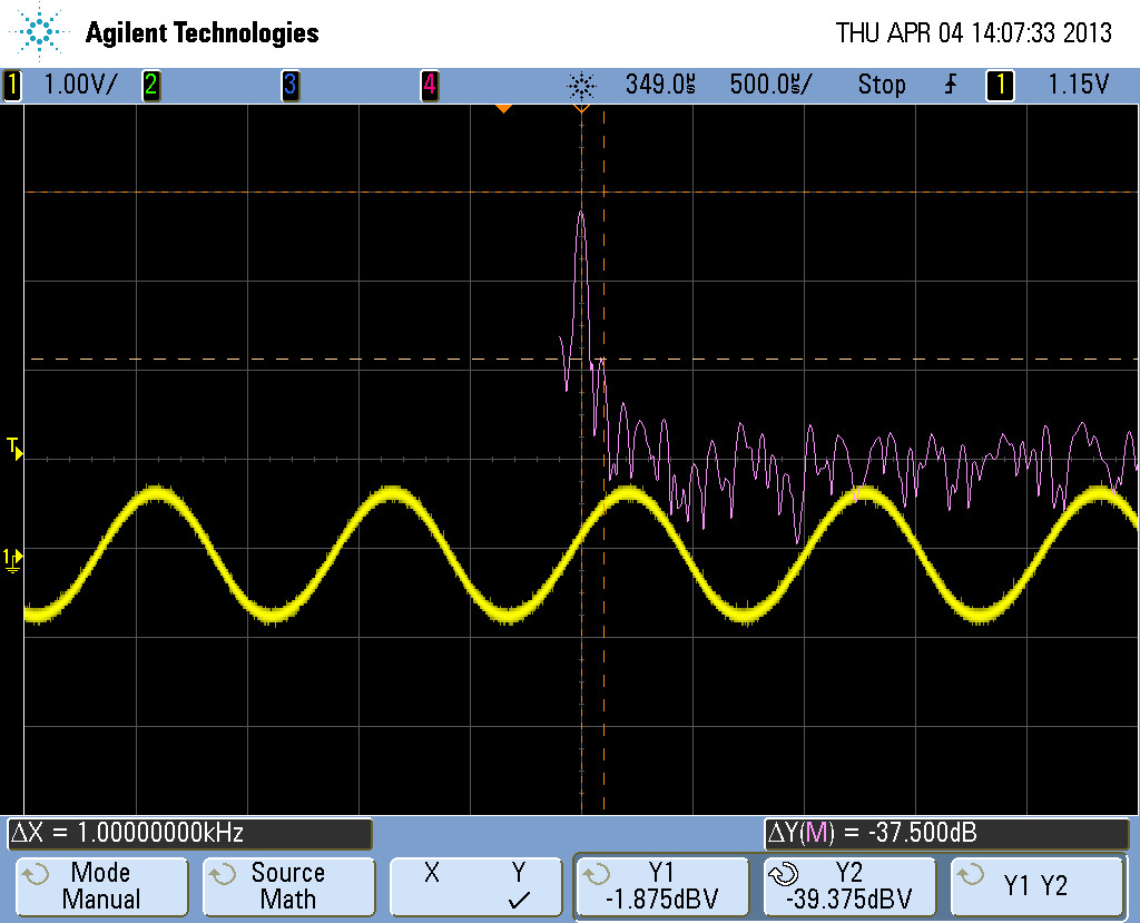
The harmonics are higher compared to the sine wave generation using NCO or look-up table methods. The PWM output produced using this method is passed through a Sallen Key filter and the output is observed using an oscilloscope. This method yields a sine wave at 1 kHz with frequency spectrum, as illustrated in Figure 12.

