3.2 Sine Wave Generation Using the Look-Up Table Method
This section describes the look-up table method for sine wave generation. This is one of the most fundamental and popular methods of sine wave generation. In this method, the values used to approximate a sine wave are stored in memory.
There are three subsets in the look-up table method:
- The first method involves the synthesis of sine waves with frequencies which are multiples of the fundamental frequency for which the table elements are calculated
- The second method involves the synthesis of sine waves with frequencies which are fractional multiples of the fundamental frequency for which the table elements are calculated. In this method, the frequencies are not integer multiples of the fundamental table frequency, and have substantially high Total Harmonic Distortion (THD).
- In the third method, the synthesis can be done for sine waves of non-integer multiples and also maintain a low THD by using interpolation
When the look-up table-based implementations are done, the entire energy of the generated sine waves will not only be at the fundamental frequency, but a small amount of the energy will also be spread out at frequencies other than the fundamental frequency. These frequencies can be both harmonic and subharmonic frequencies. The presence of these frequencies will create a certain amount of distortion in the resultant waveform.
The harmonic distortions in the resulting waveform can be attributed to two factors: quantization and sampling errors. The sine table elements are stored in data memory and have definite word length such as 8 bits, 10 bits, 16 bits, and so on. Therefore, the values of these elements cannot be exactly represented and might result in quantization errors which are related to the word length. When dealing with frequencies which are non-integer multiples of the fundamental table frequency, the sample values between the two table entries must be estimated. These calculations would introduce sampling errors. Because these estimations inherently use the table values for calculation purpose, the resulting values will have quantization errors embedded in them, and the sampling errors will always be more than the quantization errors.
In order to reduce the quantization and sampling errors, a combination of the look-up table method along with interpolation must be used. This will reduce the distortions significantly. By using interpolation, the sine values between the values of table elements can be represented more precisely. For ease of implementation, Linear Interpolation method is used mostly. In this method, the values between any two table entries are assumed to lie on a straight line.
Code Snippet for Sine Wave Generation Using Look-Up Table Method shows a code snippet for generating a sine wave at 1 kHz using the look-up table method.
Code Snippet for Sine Wave Generation Using Look-Up Table Method
// FOSC configuration: Fosc = 16 MHz using external Oscillator
    #pragma config FEXTOSC = ECH      // External Oscillator Selection bits->EC (external clock) above 16 MHz
    #pragma config RSTOSC  = EXTOSC   // Reset Oscillator Selection bits->EXTOSC operating per FEXTOSC bits

    unsigned char gDutycount =0;
    const char SINETABLE[40]= {
        50, 55, 60, 65, 70, 75, 80, 85, 90, 95,
        100, 95, 90, 85, 80, 75, 70, 65, 60,55,
        50, 45, 40, 35, 30, 25, 20, 15, 10, 5,
        0, 5, 10, 15, 20, 25, 30, 35, 40, 45};

// Timer2 configuration for PWM
    T2PR     = 0x63;      // PWM period register for 40 kHz
    T2CLKCON = 0x01;    // Timer2 clock source = Fosc/4
    T2CON    = 0x80;    // TCKPS 1:1; TMRON on; TOUTPS 1:1;
// PWM 3 configuration
    PWMTMRS0 = 0x01;    // Set the PWM to the options selected in the CTSEL PWM3timer2;
    PWM3DCH  = 0x31;    // PWMDCH 49;
    PWM3DCL  = 0xC0;    // PWMDCL 3;
    PIE1     = 0x80;    // Timer2 interrupt enable

    INTCON   = 0xC0;     // Global interrupt enable, peripheral interrupt enable
    RD3PPS   = 0x0B;    // Route the PWM3 signal to RD3
    TRISD    = 0x00;    // Port D as output port
    ANSELD   = 0x00;    // Port D as digital port
    PWM3CON  = 0x80;    // PWMPOL active_hi; PWMEN enabled;
    void interrupt Timer2_ISR(void)
    {
        if (TMR2IF)
        {
            ++gDutycount;   // Increment the counter variable by 1
            if(gDutycount == 40)
            {
                gDutycount = 0;
            }
            PWM3DCH = SINETABLE[gDutycount]; // Load the duty cycle register according to the sine table
            TMR2IF = 0;
        }
    }
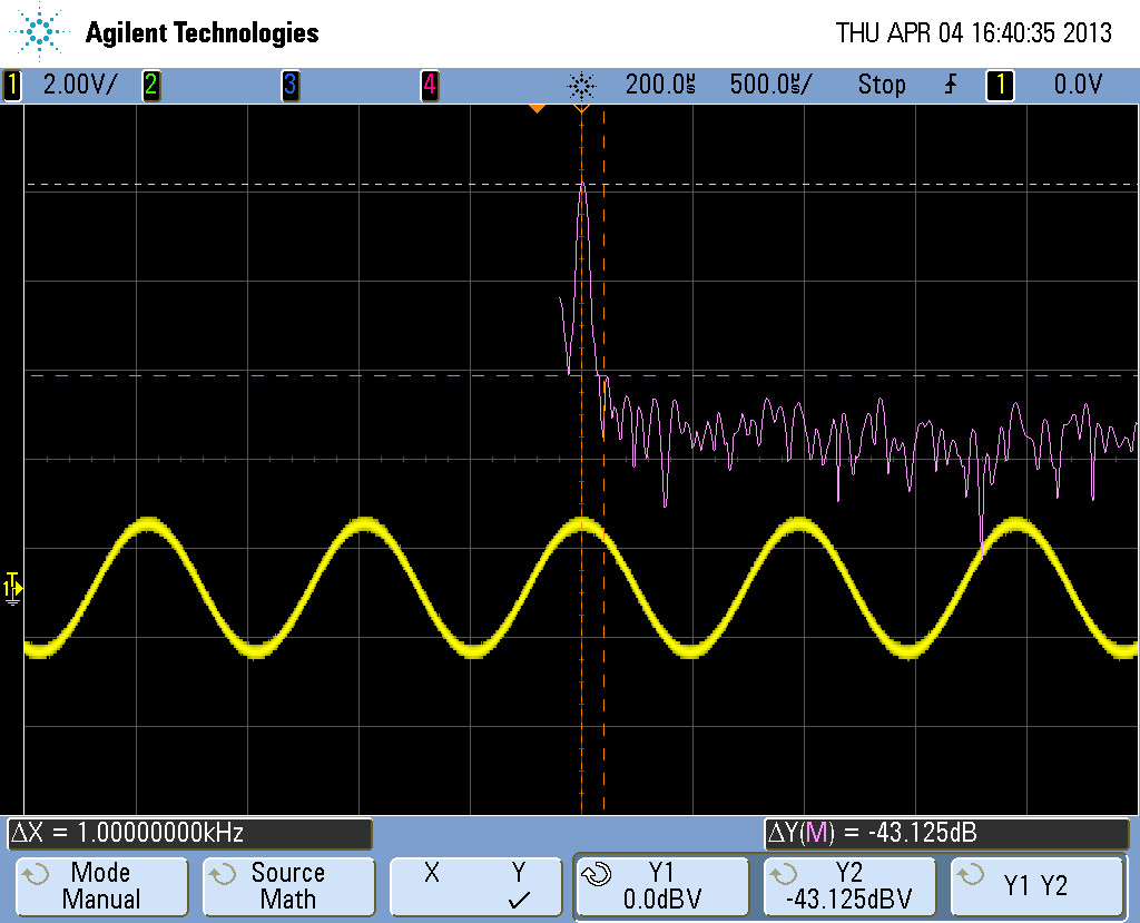
The duty cycle of the PWM is varied and is passed through a Sallen Key filter. The resulting sine wave and the frequency spectrum is illustrated in Figure 1. The resulting harmonics are slightly more than the NCO-based methods, as provided in Sine Wave Generation Using NCO Module.

