3.4.1 Harmony 3 EMAFE Direct Transfer Mode Example
This topic provides instructions and information about the MPLAB Harmony 3 EMAFE direct transfer mode demonstration application, which is included in the MPLAB Harmony Smart Energy Metrology Applications distribution.
Description
| Channel | Input Signal | Data Register |
|---|---|---|
| Channel 0 | Temperature sensor | EMAFE_DATA0 |
| Channel 1 | I1 | EMAFE_DATA1 |
| Channel 2 | V1 | EMAFE_DATA2 |
| Channel 3 | I2 | EMAFE_DATA3 |
| Channel 4 | V2 | EMAFE_DATA4 |
When enabling V1 filter, V1 filter uploads their 24-bit data in EMAFE_DATA2 register.
When a new set of data in V1 is uploaded, the flag DRDY is set in the Interrupt Status register (EMAFE_ISR). An interrupt can be triggered if the bit DRDY is written to 1 in the Interrupt Enable register (EMAFE_IER).
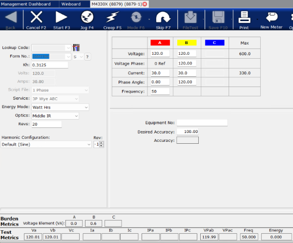
This application has been designed to capture 1600 samples, which supports 5 cycles of a periodic 50 Hz signal:
Fs = 16000 ksps. Fin = 50Hz. Fs/Fin = 320 samples/cycle. Total samples = 320 * 5 = 1600 samples in 5 cycles.
Where Fs is sampling frequency and Fin is input signal frequency.
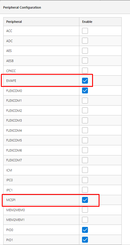
Harmony MCC Component Blocks
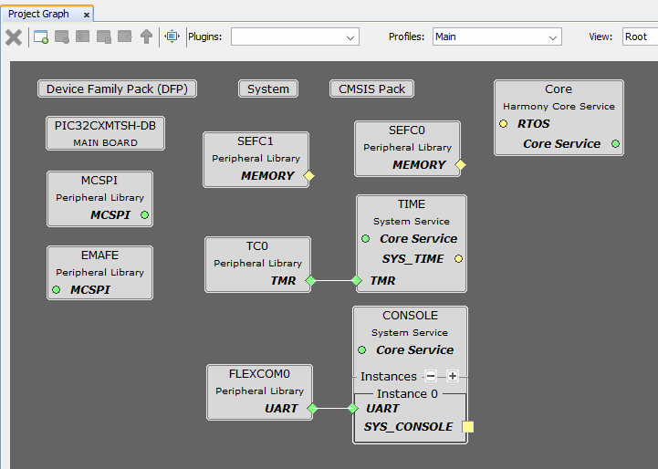
The virtual COM Port interface is enabled to provide an output console.
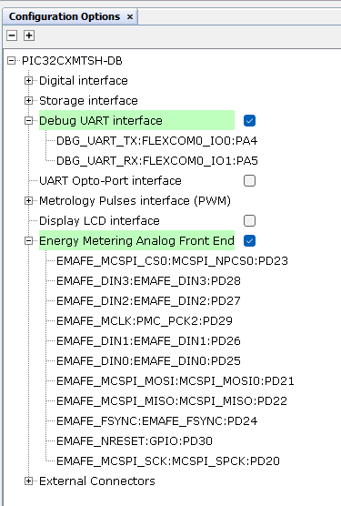
Energy Metering Analog Front End component must be enabled.
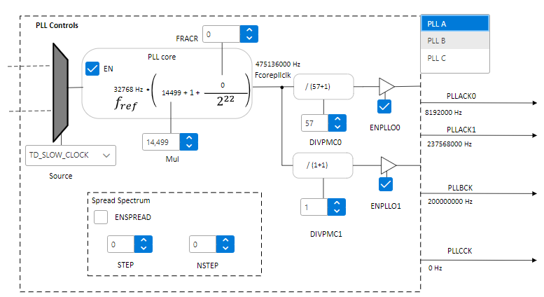
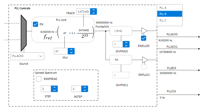
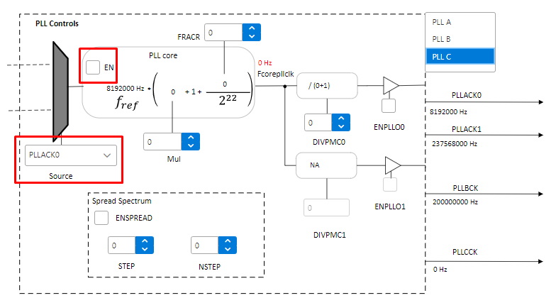
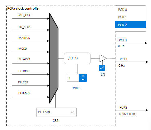
Clock Configuration
Clocks are configured to match the following distribution:
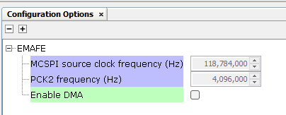
Harmony EMAFE Code Configuration Options
EMAFE peripheral library is configured to use Direct Transfer mode by disabling the Enable DMA option.
Building the Application
This section identifies the MPLAB X IDE project name and location and lists and describes the available configurations for the demonstration.
The parent folder for these files is smartenergy_metrology\apps\peripherals\emafe\emafe_polled. To build this project, the user must open the smartenergy_metrology\apps\peripherals\emafe\emafe_polled\emafe_polled_pic32cxmtsh_db.X project file in MPLAB X IDE.
MPLAB X IDE Project Configurations
This table lists and describes the supported configurations of the demonstration, which are located within ./src/config.
| Project Name | Configuration | Description |
|---|---|---|
| emafe_polled_pic32cxmtsh_db | pic32cxmtsh_db | This demonstration runs on the PI32CXMTSH Development Board. |
Running the Demonstration