5 PWM Basics
PWM is an abbreviation for Pulse Width Modulation. In this mode, the timer acts as an up/down counter. This means that the counter counts up to its maximum value and then clears to zero. The advantage of the PWM is that the duty cycle relation can be changed in a phase consistent way.
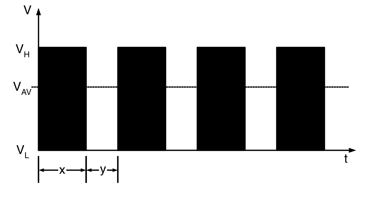
If the PWM is configured to toggle the Output Compare pin (OCx), the signal at this pin can look like shown in the following figure.

VH: Output Voltage high level
VL: Output Voltage low level
VAV: Average Output Voltage level
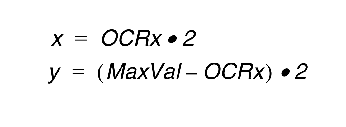
x: Duty cycle high level
y: Duty cycle low level


The fact that this method allows the timer to generate voltage levels between VCC and GND means that a DAC can be implemented using the PWM. Details about this are described in the application notes AVR314: DTMF Transmitter and AVR335: Digital Sound Recorder with AVR and Serial DataFlash.
