
10.1 RGB LED Board Support Service
This document explains how to use the MPLAB Code Configurator(MCC) framework to add RGB LED system service component for using the RGB LED on WBZ351 Curiosity board and control its colour through TCC/TC based PWM pulses. The system service helps to add the component on any applications.
Introduction
The RGB LED System service component has dependency of TCC/TC (Based on the Timer component availablity in the device) timer Plib in order to create PWM pulses based on the RGB colour values. This component, implements both HSV to RGB conversion as well as XY to RGB conversion. So, it would be useful for the Zigbee lighting control where Zigbee ZCL specification supports both HSV and XY colour co-ordinates.
Hardware Required
| Tool | Qty |
|---|---|
| WBZ351Curiosity Board | 1 |
| Micro USB cable | 1 |
Hardware Modification
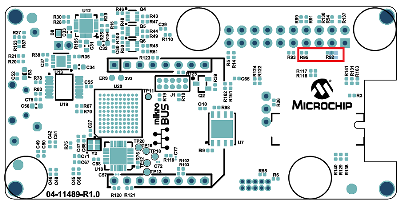
A simple hardware modification is needed to use RGB LED on WBZ351 Curiosity board. WBZ351 Curiosity boards has on-board RGB LED on PB0, PB3, PB5 pins. But, these pins are multiplexed with CVD Touch functionality. Hence the connection to R and B LED's are disconnected by default on the board. Mount 0 ohm resistor or make the solder connection on R92 and R95 resistor position as shown below.
SDK Setup
Developing an Application with RGB LED SERVICE component using MPLAB Code Configurator(MCC)
This section explains the steps required by a user to integrate and use the RGB LED SERVICE component into any application.
Tip: New users of MPLAB Code Configurator (MCC) are recommended to go through the overview of MCC. Users can add/remove different components like peripheral support and other wireless functionality by following steps mentioned here.
- Create a new MCC Harmony Project -- link for instructions
- Ensure that wireless_system_pic32cxbz_wbz repo is available locally in the H3 repo environment.
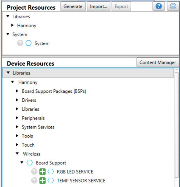
- Open MCC. The Wireless Board Support components will be displayed in available
Device Resources --> Wireless --> Board Support as shown in the below
figure.
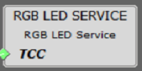
- Drag RGB LED SERVICE component
from Device Resources to project graph area and accept all Dependencies or
satisfiers(auto-activation components), select "Yes".
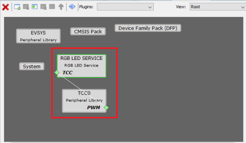
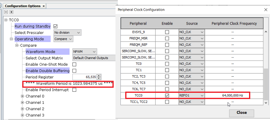
- RGB LED SERVICE connects with
TCC/TC component and does the PWM pulse configurations. Uses default Clock
configuration for TCC/TC. For example, for TCC component, REFO1 with 64MHz clock
is given to TCC. With this configuration, the PWM pulse frequency is 977
(period: 1023.98uSec). By changing the Clock frequency will change the PWM pulse
frequency.
 Note: Refer to device datasheet for PWM pulse frequency calculation
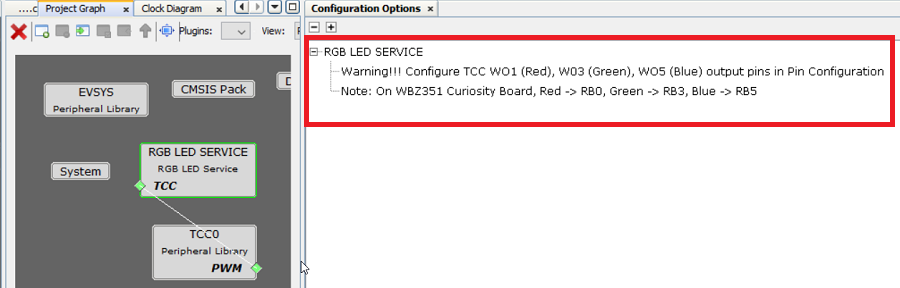
 - There will be a warning note on
the RGB LED SERVICE component. Satisfy the warning by configuring the needed
Pins connected to R,G,B LED's for the PWM waveform output.
 Note: Refer for device datasheet PPS chapter for pin configurationFor WBZ351 curiosity board,
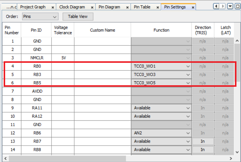
- Generate the code. Refer link for more details.
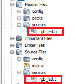
- After generating the program
source from MCC interface by clicking Generate Code, the RGB LED service can be
found in the following project directories.
- Compile and Run the project on the board
RGB LED SERVICE component API's
The below API's are available from RGB LED component, to be called from application where ever needed.
-
Turn off RGB LED.
void RGB_LED_Off(void);
-
Set brightness level
void RGB_LED_SetBrightnessLevel(uint8_t level);
-
Set the color using Hue and Saturation as parameters
void RGB_LED_SetLedColorHS(uint16_t hue, uint8_t saturation);
-
Set the color using Hue, Saturation and brightness level as parameters
void RGB_LED_SetLedColorHSV(uint8_t hue, uint8_t saturation, uint8_t level);
-
Set the color using X and Y as parameters
void RGB_LED_SetLedColorXY(uint16_t x, uint16_t y);