
5.6.1.10 Zigbee Application Demo: MultiSensor with Deep Sleep Functionality
WBZ351 Curiosity Board
Device: PIC32CX5109BZ31048 (MCU) on WBZ351 Module
On-Board: UART-USB Converter
Introduction

Hardware Requirement
| Tool | Quantity |
|---|---|
| WBZ351Curiosity Boards | 2 |
| Micro USB cable | 2 |
| Personal Computer | 1 |
Software Requirement
SDK Setup
Programming the Precompiled Hex File or Application Example
The Multisensor is an end device application. The Multisensor application works by getting connected with a Co-ordinator device (Combined Interface). So, to successfully execute this demo, it is mandatory to have a Combined Interface application set-up prior to running the Multi-sensor application.
| Attention | |
|---|---|
#define CS_BDB_PRIMARY_CHANNELS_MASK (1L << 12)
#define CS_BDB_SECONDARY_CHANNELS_MASK (1L << 12)-
One of the WBZ351 Curiosity boards is programmed with Combined Interface which can act as Zigbee Gateway/Coordinator. Program the CI pre-compiled hex image by following the steps mentioned in the “Programming the precompiled hex file or Application Example” section of the Zigbee Centralized Network Formation by Combined Interface application.
-
Program another WBZ351 Curiosity board with Multisensor application. Follow the steps mentioned below to program the curiosity board with Multisensor application.
Programming the .hex File using MPLAB X IPE
- Import and program the Precompiled
.hexfile is located in"<Harmony Content Path>\wireless_apps_pic32cxbz3_wbz35\apps\zigbee\multisensor_deepSleep\hex"folder - For more details on the steps, go to
Programming a DeviceNote: Users must choose the correct device and tool information
Programming the Application using MPLAB X IDE
-
Follow steps mentioned in the Running a Precompiled Example section
- Open and program the application example “
multisensor_deepSleep.X” located in “<Harmony Content Path>\wireless_apps_pic32cxbz3_wbz35\apps\ zigbee\multisensor_deepSleep\firmware"using MPLAB X IDEFor more details on finding the Harmony content path, refer to Installing the MCC Plugin
Demo Description
This application demonstrate the working of Zigbee Multisensor end device joining to Zigbee Coordinator (Combined Interface). After joining, Multisensor device will start ZCL attribute reporting of sensor data such as temperature, occupancy, light, and humidity.
| Application | Zigbee Logical Device Type | Functionality |
|---|---|---|
| Combined Interface | Coordinator | Device capable of controlling and monitoring other devices. It is typically a mains-powered device like a PC |
| Multisensor | End Device | Reports sensor data such as temperature, occupancy, light, and humidity periodically to Gateway |
The application demonstration is required to have a Combined Interface application up and running in the vicinity. which can act as Zigbee Gateway/Coordinator. The Multisensor application here can act as Zigbee end device.
Demo Steps: Commissioning.
The Zigbee Multi-Sensor can be connected to a Zigbee network.
Joining Multisensor with the WBZ351 Combined Interface (CI) Coordinator
Hardware and Software Setup
-
Supply power to the WBZ351 Curiosity board consisting of Combined Interface application by connecting a USB cable.
- The application activity is shown in
"Console Log" through on board UART-USB converter
- Open TeraTerm and configure as
mentioned below:Terminal Settings
- Baud Rate/Speed – 115200 (as configured in SERCOM configuration)
- Parity – None
- Data Bits – 8
- Stop Bits – 1
- Flow Control – None
For more details on how to set the “Serial Port” and “Speed”, refer to COM Port Setup
- Additionally, local echo and sending
line ends with line feeds can be enabled in the PC serial terminal application.
Figure 5-50. Tera Term Terminal Setup 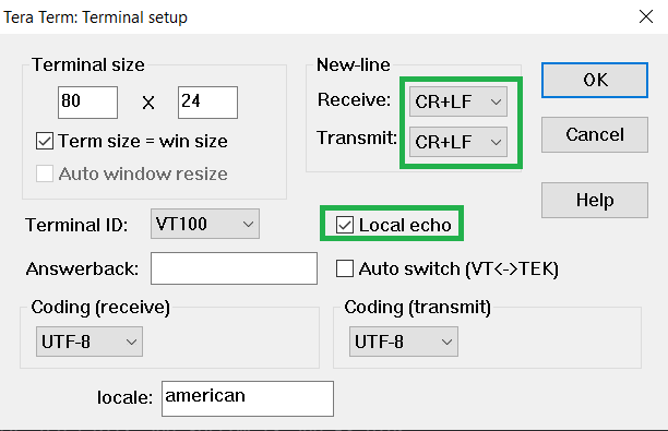
- Open TeraTerm and configure as
mentioned below:
-
Make the serial terminal ready and then press the Reset button on the Curiosity board. Below logs will be displayed.
Figure 5-51. Tera Term Logs 
Network Formation (Coordinator - Combined Interface)
Follow the steps explained in the Network Formation (Coordinator - (Combined Interface)) section to open up the network in CI.
Commissioning (End Device - Multisensor)
Supply power to the WBZ351 Curiosity board which is programmed with Multisensor image by connecting a USB cable. The Multisensor will search for Zigbee Coordinator device and will join to network and intiate Finding and Binding.
Figure 5-52. Tera Term Logs 
-
Once Multi-Sensor finishes Finding and Binding procedure, it will start attribute reporting. The Combined interface terminal log prints the received attribute information as illustrated in the following figure.
Figure 5-53. Tera Term Logs 
Developing this Application from Scratch using MCC
For developing Combined Interface from scratch, refer to the section of the “Creating Application Device Types From Scratch Using MCC” Zigbee Centralized Network Formation by Combined Interface application.
For developing the Multisensor Deep Sleep application, follow the below steps:
-
Create a new MPLAB MCC Harmony Project. For more details, refer to Creating a New MCC Harmony Project
- Option 1: Import component configuration:
This step helps users setup the basic components and configuration required to develop
this application. The imported file is of format
.mc3and is located in the path"<Harmony Content Path>\wireless_apps_pic32cxbz3_wbz35\apps\zigbee\multisensor_deepSleep\firmware\multisensor_deepSleep.X".For more details on how to import the component configuration , refer to14.3 Importing Existing App Example Configuration.
Verify the project graph and configuration options shown in the below steps.
Note: Import and Export functionality of the Harmony component configuration will help users to start from a known working setup of the MCC configuration. - Another method is manually adding and configuring the components in project graph
- From “Device Resources” field, select
+ Multi Sensor component to add it in project graph.
Figure 5-54. Multi Sensor 
-
Accept all the component auto-activation and attachment auto-connect confirmation.
Figure 5-55. Auto-Activation Requests 
Confirm Yes for all the Attachment Auto-Connect requests
Figure 5-56. Auto-Connect Requests 
- Verify if the project graph window
has all the expected components. as illustrated in the following figure:
Figure 5-57. Project Graph 
- Configure Multi Sensor component.
- Enable Deep Sleep feature.
- Fix Primary Channel and Secondary
Channel to channel
12
This is because the Zigbee console command is removed from this example to showcase minimum power consumption. Consequentially, the Combined Interface (CI) device also need to be fixed at the same channel of 12 (see ATTENTION above).
Figure 5-58. Multi Sensor Configuration 
-
System Clock Configuration and SOSC selection during sleep mode
- System Clock Selection
Figure 5-59. Clock Configuration 
- SOSC clock configuration
Figure 5-60. Clock Configuration 
- System Clock Selection
- Pin configurations/Code changes for Sleep functionality, Configure the GPIO settings
in the system configuration settings as illustrated below:
Figure 5-61. System Configuration 
These changes are made to set the default states of respective GPIO pins in consideration to save the power.
The Pin PB5 functionality must be changed to GPIO to disable the JTAG functionality for reduced power consumption.
Figure 5-62. Pin Configuration 
Figure 5-63. Pin Configuration 
- From “Device Resources” field, select
+ Multi Sensor component to add it in project graph.
Generating a Code
Now all the required components have been added to the project and necessary configuration modification is made. The next step is to generate the application code.
For more details on code generation, refer to the MPLAB Code Configurator(MCC) Code Generation section.
Files and Routines Automatically Generated by the MCC

Zigbee Stack Initialization and Application Callback Registration:
The RF System, ZIGBEE, PERIPHERAL initialization routine executed during program
initialization can be found in SYS_Initialize() of
initialization.c file.
Zigbee_Init() from initialization.c is
called.initialization.c
app.c
app.c file is autogenerated and
has a state machine for application callback handling from Zigbee stacksapp.c
User Application Development
This section talks about the mandatory code modifications that need to be incorporated in order to implement the sleep mode functionality.
- Include
definitions.hin all the files where UART will be used to print debug information
Note:definitions.his not specific to just UART peripheral, instead it must be included in all application source files where peripheral functionality will be exercised -
app_user_edits.c-
Some of the Harmony 3 generated files cannot be fully configured by the . This file contains the instructions for the user to modify these files.
Follow the instruction mentioned on the app_user_edits.c file and after completing the required edits, comment out or remove the #error line. Also see User Action
-
-
zigbeeAppDeviceSelect.h- Default Generated: “#define CS_UID 0 //Unique Identifier (UID) determining the device extended address”
- Change to a unique value: “#define CS_UID 0x123bee //Unique Identifier (UID)
determining the device extended address”
Figure 5-68. zigbeeAppDeviceSelect.h
Reason: By default, the coordinator also has the same value. In a network the UID value must be unique
Note: The below modifications are specific to the Deep Sleep Mode feature.
initialization.cIn the function ‘
SYS_Initialize’, cut the lines from 369 to 372 and place it inside the function ‘_on_reset’ after line 304 as illustrated in the following figureFigure 5-69. initialization.c
heap_4.cUpdate the declaration of ucHeap (line 64) with this attribute: ‘__attribute__((section (".bss.ucHeap"), noload))’. Refer to the following figure.Figure 5-70. heap_4.c
stackConfig.h(optional)If the deep sleep period has to be increased/decreased according to the requirements, then it has to be changed in the
stackConfig.hfile as mentioned below. Make sure that theCS_DEFAULT_END_DEVICE_TIMEOUTvalue must be three times greater than theCS_END_DEVICE_SLEEP_PERIOD. For example, if the Device deep sleep period is 1 min, then the End device timeout period must be greater than 3 min.Figure 5-71. stackConfig.h