
9.1 Bootloader
Introduction
A bootloader is a small application that can be used to upgrade firmware on a target device without the need for an external programmer or debugger. For PIC32CXBZ3/WBZ35 standalone bootloader, it provides below functionalities:
Device Firmware Upgrade over Serial(UART) interface, this is also called DFU over Serial.
Provide functionality support for wireless Over The Air Update, which is also called OTAU.
Provide various approaches to verify and authenticate firmware if enabled.
Display Console message if enabled
PIC32CXBZ3/WBZ35 Standalone Bootloader Component
PIC32CXBZ3/WBZ35 bootloader is a standalone Harmony component used to configure bootloader code for PIC32CXBZ3/WBZ35 device. Click here to know about PIC32CXBZ3/WBZ35 standalone bootloader component, user can find more information as listed below:
Memory layout of PIC32CXBZ3/WBZ35 device
Boot memory information
Image metadata definition
Working of Bootloader
Flow diagram of Bootloader
Bootloader configuration options
Bootloader and DFU API usage
Functionality of Bootloader
- Loads firmware images to embedded flash/external flash over the serial connection using a tool or python script, known as Device Firmware Upgrade (DFU)
- Provides application protection for firmware (Secured device)
- Upgrades application firmware to newer revision
- Controls which application can run based on Sequence number and other metadata information embedded in the OTA image.
BootPIC32CXBZ3/WBZ35loader Example Code
bootloader provided two methods to enter DFU mode, one is GPIO Trigger, another is Timber Based Trigger. Later section will have more detailed information about them.
For bootloader using GPIO Trigger method, user can find example code in wireless_apps_pic32cxbz3_wbz35\apps\bootloader\bootloader, and precompiled hex file at wireless_apps_pic32cxbz3_wbz35\apps\bootloader\bootloader\precompiled_hex\bootloader.X.production.hex
For bootloader using Timer Based Trigger method, user can find a precompiled hex file at wireless_apps_pic32cxbz3_wbz35\apps\bootloader\bootloader\precompiled_hex\bootloader_timer.X.production.hex. Since Timer Based Trigger bootloader creation is very similar to GPIO Trigger, there is no example code provided for it.
Creating Bootloader From Scratch Using MCC
This section explains the steps required by a user to configure and generate a PIC32CXBZ3/WBZ35 standalone bootloader from scratching using MCC. User can find the bootloader example code(GPIO Trigger) generated using MCC in the path wireless_apps_pic32cxbz3_wbz35\apps\bootloader\bootloader
Enabled UART DFU
Enabled console to display messages
Enabled GPIO Trigger
Hardware requried is WBZ351 Curiosity Board, DFU mode is triggered by pressing SW3(GPIO PA4) on the board
Automatically reboot firmware after DFU is finished
WBZ351 Curiosity Board Top View

Followings are steps to create the bootloader example(GPIO Trigger) from scratch.
Tip: New users of MPLAB Code Configurator are recommended to go through the overview.
1. Create a new MCC Harmony Project -- link for instructions, selecting WBZ351 as Target Device.
2. After MCC is launched, in Device Resource window, expand Harmony – Wireless – PIC32CX-BZ System Services , select Bootloader and add the component.
Harmony-Wireless-PIC32CX-BZ System Services , select Bootloader

Click all YES

4. After completing auto-activation, the resulting project graph is as below.

5. Select bootloader component and satisfy the UART dependency (sercom0 for WBZ351 curiosity board)
6. Default configuration - UART DFU is connected to Port A, Pin 4; this is SW3 on WBZ351 curiosity board
GPIO Trigger is the option to trigger DFU mode, where user needs to hold the GPIO button during reset to put the bootloader into DFU mode. Use GPIO Port and GPIO Pin option to change the port and pin based on user hardware.
Tip: Other than GPIO Trigger, another trigger option Timer Based Trigger is also provided, where bootloader will be in DFU mode for amount of time before jumping to the user application. User can change the DFU Wait Time in Milliseconds to change the amount of time. By selecting Timer Based Trigger, a 32bit timer component TC0 is asked to be activated, click YES to accept adding TC0 and accept its connection. Following figures show Timer Based Trigger options and message prompt of adding TC0.

7. Click on the SERCOM0 component and Configure the Baud rate if required (default is 115200)

8. Check the configuration option for QSPI_BAUD_RATE (default is 16 MHz)

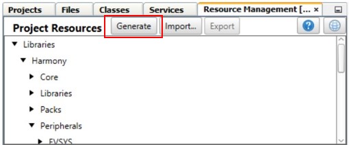
9. In project resources, select Generate option.
Press MCC Generate Button to Generate the Code
10. After project files generation has been completed, go to project properties, and select boot flash option from the header pane.

11. Configure MD_SEQ_NUM as desired.
For applications that require to always jump to the bootloader from ROM, ensure that this number is smaller than the application images
Example:
Bootloader MD_SEQ_NUM = 0x00000001
Application MD_SEQ_NUM = any value greater than 0x00000001
For applications scenario where ROM firmware needs to jump to bootloader only if there is no other valid application; make sure that the application MD_SEQ_NUM is smaller than the bootloader MD_SEQ_NUM.
Example:
Bootloader MD_SEQ_NUM = 0xFFFFFFFE
Application MD_SEQ_NUM = any value smaller than 0xFFFFFFFE
After programming MD_SEQ_NUM, select OK

12. On the IDE Tools bar, click Clean and Build Main Project to build the code.
Click Clean and Build Main Project to Build Code
While generated bootloader hex file should be added to user aplication as Loadable File, they shouldn't be used alone. Followings are talking about a few simple steps need to be handled at user application side.
Configure User Application to Use Bootloader
To use Bootloader with a user application, there are a few steps to be configured at user application project. These steps are common to any user application that wants to have Bootloader capability, these steps include:
Add Bootloader Services component onto user application project and generate code
Add Bootloader as Loadable File/Project to create unified image
Program unified image to device.
Add Bootloader Services Component and Generate Code
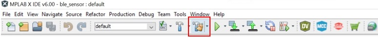
Open any user application project with MPLAB X IDE, click on MCC icon on Tools bar to launch MPLAB Code Configurator to open project graph.
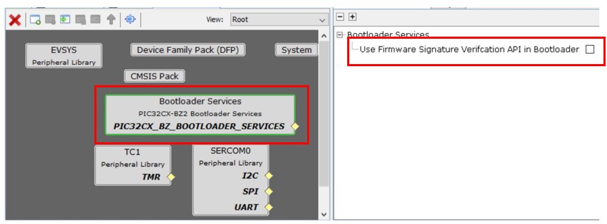
In Device Resource window, expand Harmony – Wireless – Driver, select Bootloader Services component and add it. This component generates the supporting linker file and MPLABX script needed for adding metadata header into application image(Project Properties is added with SignFirmware settings). Use Firmware Signature Verification API in Bootloader is the only option in Bootloader Services component. For DFU via UART, it is not necessary to enable firmware signature and verification, although user can do so if needs. While for OTAU, user must enable firmware signature and verification, by clicking on check box to Use Firmware Signature Verification API in Bootloader.
(Following project graph is just an example, user may have different graph depending on their application.)
Add Bootloader Services and Configure
After Bootloader Services component is added and configured, press Generate button to generate the user application code. In the generated new code, some code about bootloader service is added, as well as project’s linker script file is also automatically changed to reflect bootloader functionality.
Press Generate button to Generate User Application Code
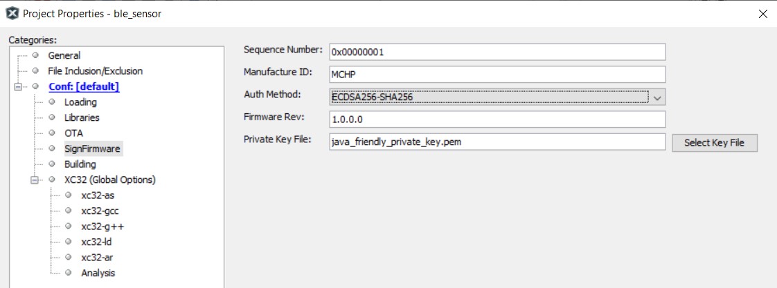
ECDSA256-SHA256: firmware signature validation and data integrity check.
SHA256: firmware data integrity check.
None: no security, no integrity check.
Firmware signature and integrity check
Firmware integrity check

Add Bootloader as Lodable File/Project to Create Unified Image
Once the new code is generated and configured, user need to add Bootloader as a loadable project/loadable hex file in the updated project. This enables MPLAB X IDE to merge both user application and bootloader and make an unified firmware by creating an unified image file.
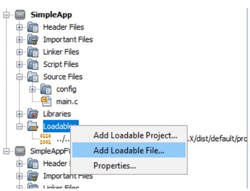
To add Bootloader as loadable file, expand application project’s tree, right click Loadables, select Add Loadable File, then browse and add the bootloader hex file.
Right Click Loadables and Add Loadable File
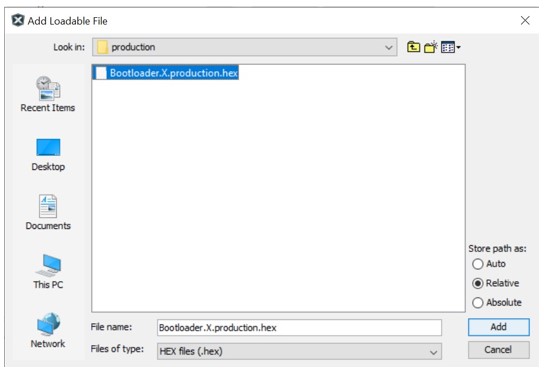
Select Bootloader Precompiled Hex File as Loadable File
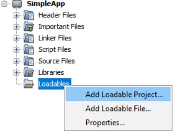
Right Click Loadables and Add Loadable Project
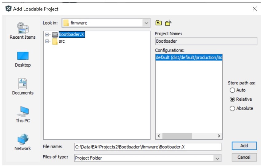
Select Bootloader Project as Loadable Project
Unified Image Merged Both User Application and Bootloader
Program Unified Image
Click Make And Program Device Main Project to Program Unified Image
