16.2 Porting Guide for WBZ451 to WBZ450
Introduction
This document provides the steps that helps the user to port an existing project created for WBZ451 to WBZ450. Before starting the porting process, ensure the peripherals and pin configurations in the WBZ451 application are supported by WBZ450 board. For available peripherals and pin details, refer to WBZ45x datasheet.
-
Open an existing WBZ451 MCC project in MPLABx.
-
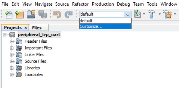
Open Project properties by selecting customize option available in the drop down options.
-
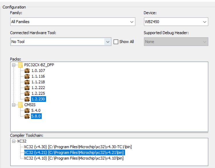
Change the Device name to WBZ450 and select the respective packs and compiler versions.
-
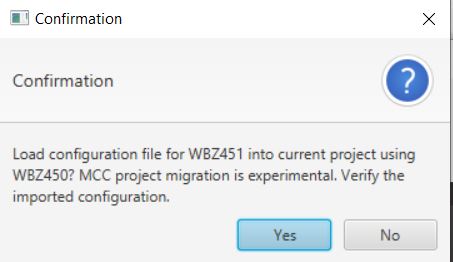
Open the MCC by pressing the MCC button available at top in MPLABx and Accept('Yes') the project migration confirmation.
While opening the MCC content manager, Untick the "Skip DFP and CMSIS Selection" option in Harmony Framework Path selection window to Manually select the DFP path.

- Choose the dfp path(by Pressing 'Choose Path') to **Harmony Framework**(H3
framework stored in the
disk)**\dev_packs\Microchip\PIC32CX-BZ_DFP\1.2.222\WBZ450\atdf\WBZ450.atdf** and
Press 'Next'.
 Note: The DFP path selection will not allow to select the folder path, In that case Manually choose the path till "dev_packs\Microchip\PIC32CX-BZ_DFP\1.2.222\WBZ450\atdf" and Manully include "\WBZ450.atdf" in the DFP path selection window.
 Choose the default selected CMSIS path and press 'Next'.

- Once MCC is opened the DFP will be available for the selected device, can be
seen by clicking on the DFP from project graph.

-
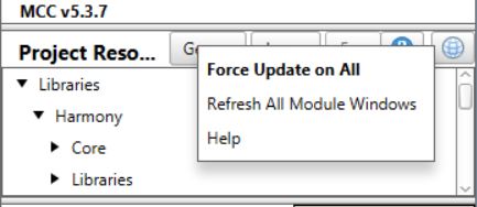
Save MCC configuration and enable **Force update on All** option(by right clicking onto the Project Resources Tab). Press Generate.
- Merge all the code differences illustrated in the merge window except Application files
-
Build and Flash the Project onto the device.
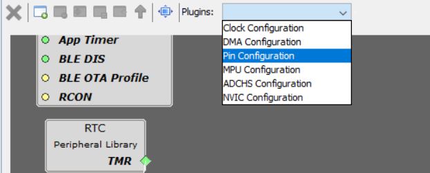
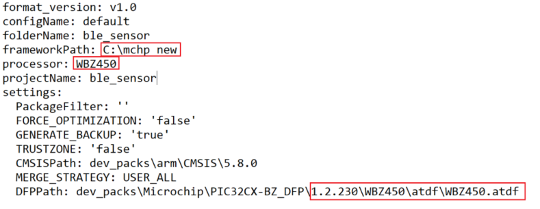
Note: To ensure accurate Pin configuration for WBZ450 after the porting process, please open the MCC window and check the Pin configuration setting. If the Pin Table/Pin Diagram is empty or the window fails to load, you may need to manually verify the DFP path in the settings.yml file located in the<app_name>\firmware\src\config\default\default.mhcfolder. Edit the DFP path and processor name as needed. Please note that for some versions of MCC, this verification may need to be done manually. Close MCC window and reopen it.
For further guidance, refer to the following diagrams.
Peripheral Pin Select (PPS) Setting
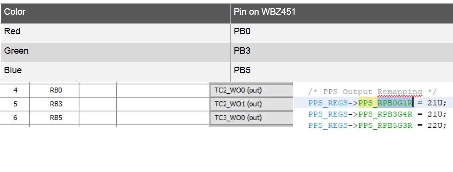
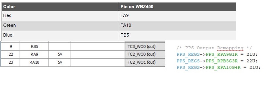
This segment provides instructions on how to remap Pin configuration. The code generation for WBZ450 depends on the correct configuration of the PPS pin settings related to the features of the application. For instance, the RGB LED feature of WBZ451 ble sensor application requires the appropriate mapping of the PPS pins for WBZ450. The developer must verify that all the PPS pin settings are accurate for WBZ450 during this porting process.
