
1.2.1 MCC Project Configuration
The following figure shows the MCC project graph of Modem App for PIC32CXMTG-EK:
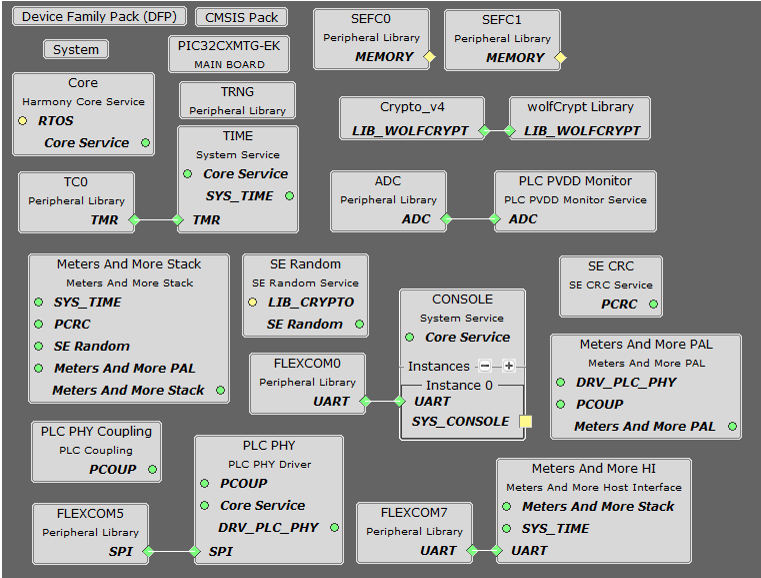
- The PLC PHY driver is needed to manage the PLC device and transmit PLC frames
- The PLC PVDD Monitor service is needed to monitor the PVDD voltage of PL460 in order to disable PLC transmission in case the voltage is not in the expected range, to avoid PL460 damage. If the PVDD voltage is in the expected range the PLC transmission is enabled
- The PLC PHY Coupling service is needed to configure the PLC transmission parameters for the selected transmission coupling branch
- The Meters And More Stack contains all code and libraries for Communications Stack
- Meters And More Host Interface provides the Serial Interface used by Modem to communicate with the External Host device
- The Console system service used output information messages from Application
- The Time system service is required by the PLC PHY driver. It is also used for timer control on Meters And More Stack and Application
- Crypto_v4 and wolfCrypt provide cryptography services used by Meters And More Stack
- The TRNG Peripheral Library is used to generate random data for frame transmission
- The CRC Service is used for CRC generation and validation in both Meters And More Stack and Host Interface
The following sections describe how Components are added and configured for this application.
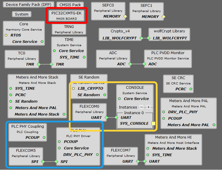
PIC32CXMTG-EK Board Component
This Component defines the board capabilities.
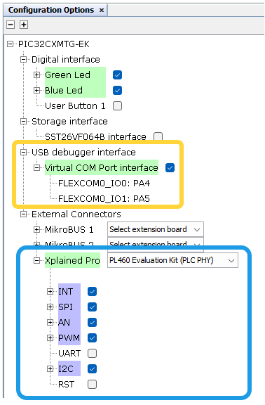
Digital Interface
Green and Blue Leds are selected, so corresponding PIOs are named and configured accordingly.
USB Debugger Interface
- Console System Service is added to Project Graph
- Flexcom0 Peripheral Library is added to Project Graph
- These components are linked
and automatically configured
Figure 1-36. Console Automatically Configured 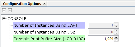
Figure 1-37. Flexcom0 Automatically Configured 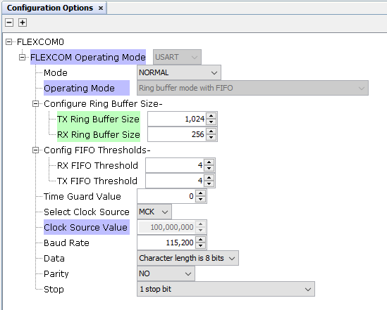
Note that buffer sizes are increased manually for this application
- All related PIOs are automatically configured
Xplained Pro Interface
PL460 Evaluation Kit at PHY level is selected to be connected to the Xplained Connector.
- PLC PHY Driver is added to Project Graph
- Flexcom5 Peripheral Library is added to Project Graph
- These components are linked and automatically configured
Figure 1-38. PLC PHY Automatically Configured 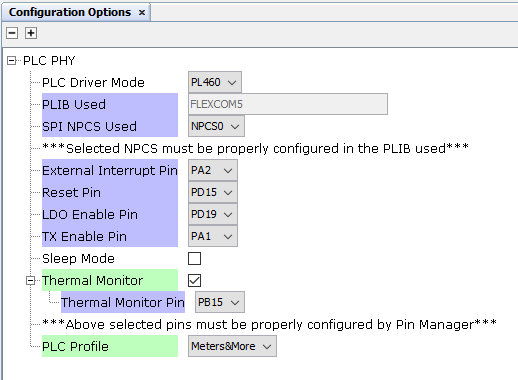
Figure 1-39. Flexcom5 Automatically Configured 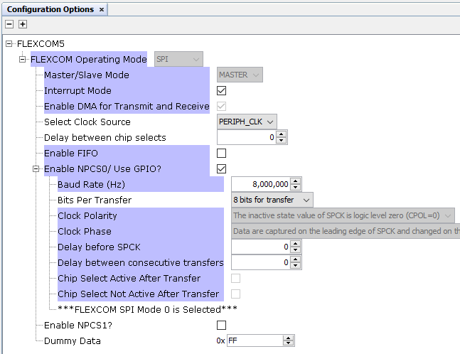
Note that Thermal Monitor is manually enabled, and Meters&More profile selected for this application
- PLC PVDD Monitor Service is added to Project Graph
- ADC Peripheral Library is added to Project Graph
- These components are linked
and partially configured
Figure 1-40. PVDD Monitor Partially Configured 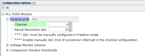
Figure 1-41. ADC Manually Configured 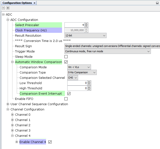
Note that Prescaler and Automatic Window Comparison are manually Configured. For Comparison, only the Event Interrupt has to be enabled, the rest of parameters will be overwritten by the PVDD Monitor after initialization, so provided values in this configurator are not used.
- All related PIOs are automatically configured
PLC PHY Coupling Component is not automatically added, it is manually added to the project.
Additional Components
- Harmony Core Service
- TRNG Peripheral Library
- TIME System Service
- TC0 Peripheral Library
connected to TIME Service and configured as shown:
Figure 1-42. TC0 Configuration 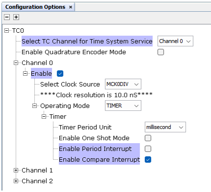
- Meters And More Stack has to be added and configured as shown (depending on
desired role, DCU or Meter):
Figure 1-43. Meters And More Stack Configurations 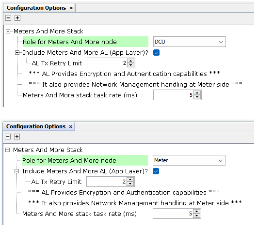
- Host Interface Component has to be added and configured as shown:
Figure 1-44. Host Interface Configuration 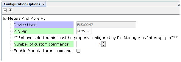
- As seen above, Flexcom7 is connected to Host Interface, and configured as
shown here:
Figure 1-45. Flexcom7 Configuration 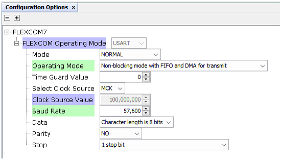
- For Cryptographic services,
Crypto_v4 and wolfCrypt Library are added. These modules are configured
differently if AES algorithms are computed by hardware or by software:
- AES by Hardware: If the MCU supports AES by Hardware (PIC32CXMT for
instance), AES-ECB and AES-CTR can be enabled in Crypto_v4
configuration. AES-CMAC has to be enabled in wolfCrypt Library.
Figure 1-46. Crypto_v4 Configuration (AES by Hardware) 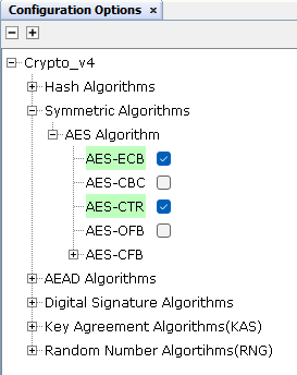
Figure 1-47. wolfCrypt Library Configuration (AES by Hardware) 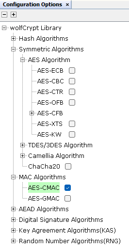
- AES by Software: If the MCU does not support AES by Hardware (SAMD20
for instance), AES-ECB and AES-CTR has to be enabled in wolfCrypt
Library configuration. AES-CMAC has to be enabled also in wolfCrypt
Library.
Figure 1-48. wolfCrypt Library Configuration (AES by Software) 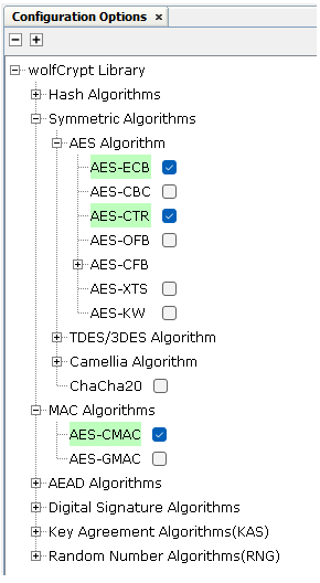
- AES by Hardware: If the MCU supports AES by Hardware (PIC32CXMT for
instance), AES-ECB and AES-CTR can be enabled in Crypto_v4
configuration. AES-CMAC has to be enabled in wolfCrypt Library.
- SE CRC Service has to be added to provide CRC capabilities