
1.1 PHY TX Test Console
The PLC PHY Tx Test Console is an application example that demonstrates the complete performance of the Microchip Meters And More PHY Layer, avoiding timing limitations in the PC host. That way, users can perform more specific PHY tests (e.g., short time interval between consecutive frames).
The following table shows the available PHY Tx Test Console projects:
| Path | Boards |
|---|---|
| smartenergy_metersandmore_apps\apps\phy_apps\phy_tx_test_console\firmware\pic32cx_mtg_ek_pl460.X | PIC32CXMTG-EK + PL460-EK |
| smartenergy_metersandmore_apps\apps\phy_apps\phy_tx_test_console\firmware\pic32cx_mtsh_db_pl460.X | PIC32CXMTSH-DB + PL460-EK |
| smartenergy_metersandmore_apps\apps\phy_apps\phy_tx_test_console\firmware\sam_d20_xpro_pl460.X | SAMD20-XPRO+ PL460-EK |
The PHY Tx Test Console application offers an interface to the user by means of a command line console. In this console, the user can configure Transmission parameters, enable Sniffer mode, perform Tx Calibration, or review current configuration. The following figure shows the console configuration menu:
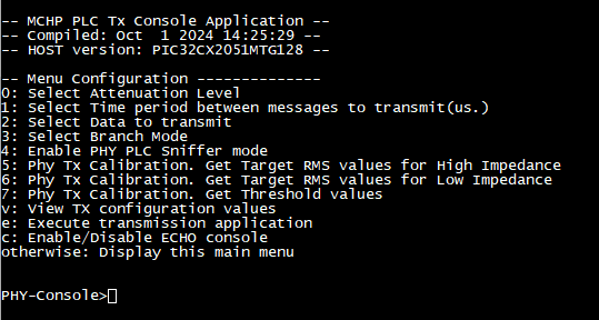
Following sections detail each of the available options in this menu.
Select Attenuation Level
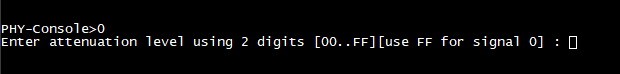
Valid range is 00 to 1F, where 00 means no attenuation, 1F means 31dB attenuation and any value in between is the value itself in dB. FF is a special value which means setting PLC Driver in transmission mode, but injecting no signal.
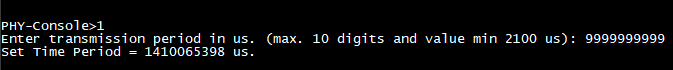
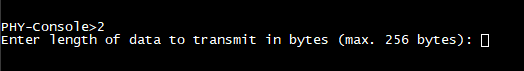
Select Time period between messages to transmit
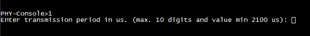
Valid range is from 2100 to 9999999999 microseconds. This is the time the transmitter will wait between the end of a transmitted frame and the start of the next one.
Select Data to transmit
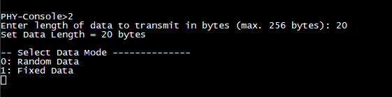
- 0 - Random Data. Transmitted bytes are selected randomly.
- 1 - Fixed Data. The sequence [0x30, 0x31, …, 0x39, 0x030, 0x31, …] is sent, up to number of bytes selected in the previous step.
Select Branch Mode
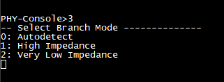
- 0 - Autodetect. Impedance is detected on first transmission and branch automatically selected.
- 1 - High Impedance. This branch is used regardless of the actual impedance in line.
- 2 - Very Low Impedance. This branch is used regardless of the actual impedance in line.
Enable PHY PLC Sniffer mode
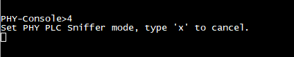
As seen on the capture, pressing ‘x’ exits Sniffer Mode and returns to main menu.
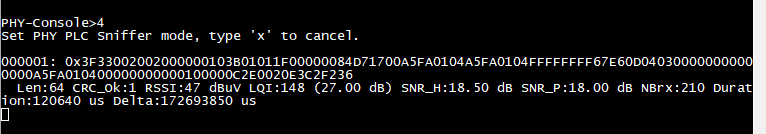
- Frame number (000001). Counter sequentially incremented at each received frame.
- Received Raw Data. Data as received in PHY layer, no decoding is done.
- Related parameters:
- Frame length.
- CRC correctness.
- Received Signal Leven, in dBμV.
- Link Quality Indicator and the corresponding SNR in dB.
- SNR measured in frame Header.
- SNR measured in frame Payload.
- Distance between frame start and Mains zero-cross (NB) [See NB definition and usage in Meters And More Specs].
- Frame duration, in μs.
- Time between previous and current frame, in μs.
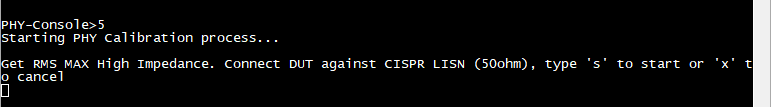
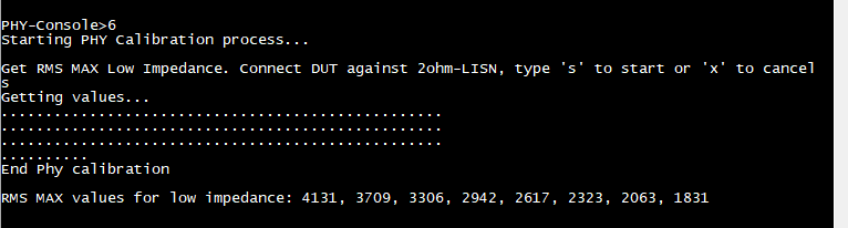
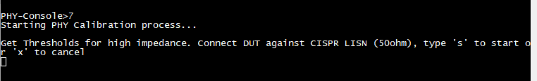
Phy Tx Calibration
Phy Tx Console application allows to perform a calibration to set the correct values to PLC Coupling parameters.
Coupling parameters are set by default to match PL460-EK characteristics, but a new calibration needs to be performed in case another Coupling configuration is used.
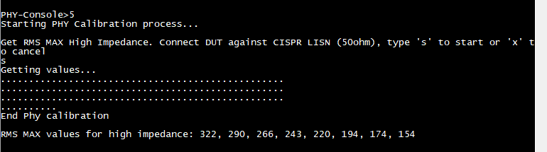
- RMS values for High Impedance
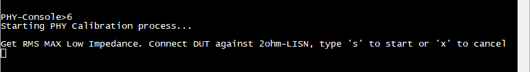
- RMS values for Low Impedance
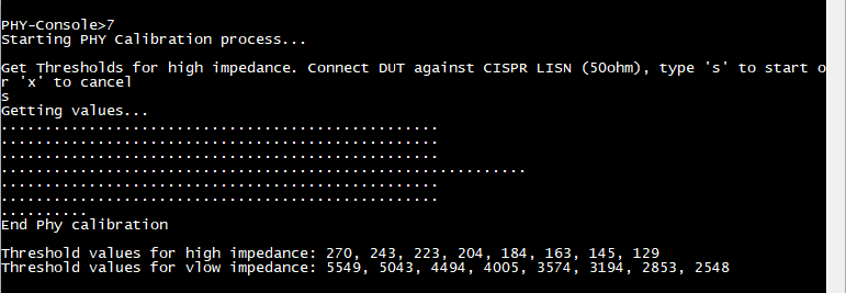
- Threshold values for Branch switching
Refer to PLC Coupling documentation for information regarding Coupling parameters and how to set proper values.
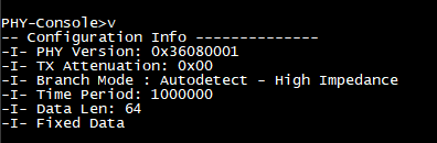
View TX configuration values
Execute transmission application
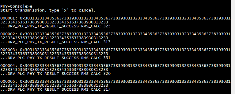
- Frame Counter.
- Transmitted Raw Data.
- Transmission result.
- RMS Calc Value. See PLC Coupling documentation for more information about this parameter.
Pressing ‘x’ exits this mode and shown the Main Menu again.
Enable/Disable ECHO console
Pressing ‘c’ Enables/Disables echo from keyboard input in Console.
By default, echo is enabled to visually verify inputs.