The icons available across the top of the Floorplanner View window allows
you to zoom in, zoom out, assign I/O banks, runs DRC checks, and create regions for
placement.
The following figure shows floorplanner view icons.
Figure 9-37. Floorplanner View Icons
The following table lists the functions of each icon.
Table 9-7. Floorplanner View Icons
Icon
Name
Function
Rubber Band Zoom
Rubber Band Zoom - Drags out an area to enlarge/zoom into.
Rubber Band Select
Rubber Band Select an area to Zoom into. Click in the Floorplanner View and drag the mouse to delineate an area. Release the mouse and all macros inside the delineated area are selected.
Works in the Macro Manipulation Mode.
Zoom In
Zoom In to canvas.
Zoom Out
Zoom Out of canvas.
Zoom to Fit
Zoom to fit the canvas size.
Zoom to Location
Zoom to a Location Specified by X-Y co-ordinates.
Zoom to fit Selection
Zoom to fit selected macros and ports. When enabled, the view attempts to center the view on the selected and placed ports.
Check Design Rules
Run the Prelayout Checker, a preliminary check of the netlist for possible Place and Route issues.
Check DRC Rules for Selected Interfaces
Check the DRC Rules for selected interfaces.
I/O Bank Settings
Set the I/O bank to specific I/O Technology.
Auto Assign I/O Bank
Run the Auto I/O Bank and Globals Assigner.
Assigns a voltage to every I/O Bank that does not have a voltage assigned to it
and if required, a VREF pin.
Collapse Visible Views
Collapse the visible views.
Expand Selected Items in Visible
Views
Expand selected Items in the visible
views.
Create Empty
Create an empty user region.
Create Inclusive
Create an inclusive user region.
Create Exclusive
Create an Exclusive user region.
Delete
Delete the selected user region.
Show Nets For Macros
Show all nets connected to the macro. There
are often many nets attached to the macro, and it is off by default.
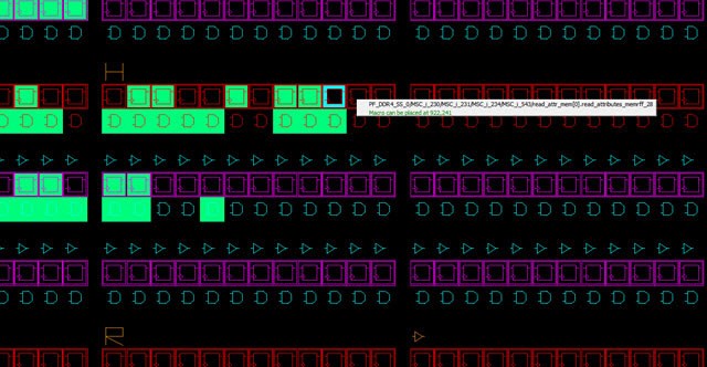
An object or a collection of the objects in the Design View window can be selected and placed in any location that is legal.
The following figure shows an example of a successful placement into the Floorplanner View.
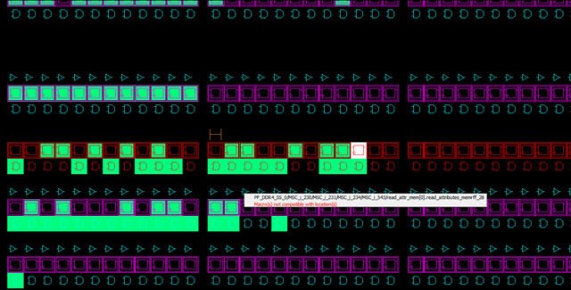
The following figure shows an example of an unsuccessful placement
attempt into the Floorplanner View.Figure 9-39. Floorplanner View - Unsuccessful Placement Attempt