
5.7 Configure Hardware
(Ask a Question)The following sections provide information about configuring the hardware for your designs.
5.7.1 Programming Connectivity and Interface
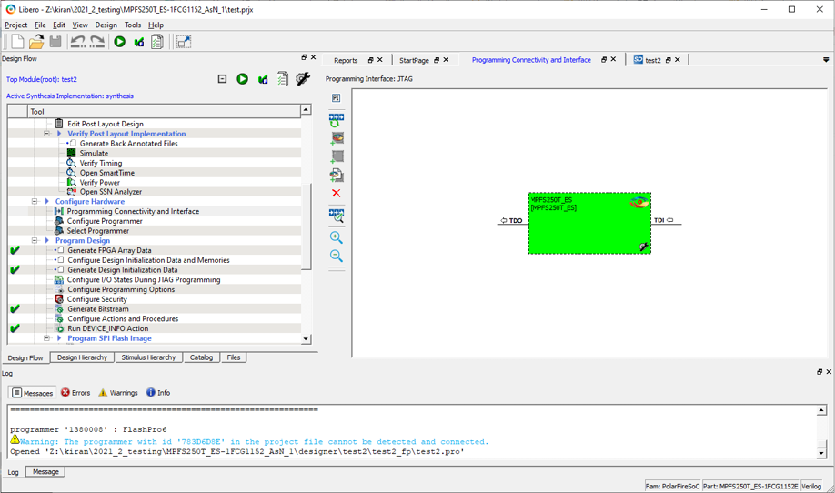
(Ask a Question)The Programming Connectivity and Interface window shows the physical chain from TDI to TDO or SPI Slave configuration. To open this window, expand Configure Hardware in the Libero SoC Design Flow window, and then double-click Programming Connectivity and Interface.
The Programming Connectivity and Interface view provides options for performing the following actions on non-target devices.
| Option | Icon | Description |
|---|---|---|
| Select Programming Interface |
 | Select JTAG or SPI Slave mode. SPI Slave mode is supported by FlashPro6 for PolarFire devices. JTAG is the default interface. |
| Construct Chain Automatically |
 | Constructs the physical chain automatically. |
| Add Microsemi Device |
 | Adds a Microchip device to the chain. |
| Add Non-Microsemi Device |
 | Adds a non-Microchip device to the chain. |
| Add Microsemi Devices From Files |
 | Adds a Microchip device from a programming file. |
| Delete Selected Devices |
 | Deletes selected devices in the grid. |
| Scan and Check Chain |
 | Scans the physical chain connected to the programmer and check if it matches the chain constructed in the grid. |
| Zoom In |
 | Zooms into the grid. |
| Zoom Out |
 | Zooms out of the grid. |
5.7.1.1 Hover Information
(Ask a Question)If you hover your pointer over a device in the grid, the device tooltip shows the following device information.
| Tooltip | Description |
|---|---|
| Name | User-specified device name. If you have two or more identical devices in your chain, use this field to give them unique names. |
| Device | Name of the device. |
| File | Path to the programming file. |
| Programming action | When a programming file is loaded, select a programming action for any device that is not a Libero design device. |
| IR | Length of the device instruction. |
| TCK | Maximum clock frequency, in Hz, to program a specific device; Libero uses this information to ensure that the programmer operates at a frequency lower than the slowest device in the chain. |
5.7.1.2 Device Chain Details
(Ask a Question)The device within the chain contains the following details.
| Detail | Description |
|---|---|
| Libero design device | Red circle within Microsemi logo. Libero design device cannot be disabled. |
| Left/right arrow | Moves the device left or right according to the physical chain. |
| Enable device | Enables the device for programming.
|
| Name | Name of your specified device. |
| File | Path to the programming file. |
| Set as Libero Design Device | Sets the Libero design device when there are multiple identical Libero design devices in the chain. |
5.7.1.3 Right-Click Options
(Ask a Question)The following figure shows the options that appear when you right-click on your design.
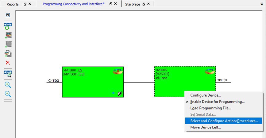
Right-clicking a device displays the following options.
| Option | Description |
|---|---|
| Set as Libero Design Device | Sets the Libero design device when there are multiple identical Libero design devices in the chain. |
| Configure Device | Reconfigures the device. For a Libero SoC target device, the dialog box appears, but only the device name can be edited. |
| Enable Device for Programming | Enables the device for programming.
|
| Load Programming File | Loads the programming file for the selected device. This option is not supported for Libero SoC target design devices. |
| Set Serial Data | Displays the Serial Settings dialog box, where you can set your serialization data. |
| Select and Configure Action/Procedure | This option applies to devices other than the Libero SoC target
design device. Choices are:
|
| Move Device Left/Right | Moves the device in the chain to left or right. |
5.7.2 Programmer Settings
(Ask a Question)For the JTAG interface, you can set specific voltage and force TCK frequency values for your programmer. For the SPI Slave interface, you can set specific voltage and force SCK frequency values for your programmer. You perform these actions using the Programmer Settings dialog box.
To display the Programmer Settings dialog box, in the Libero SoC Design Flow window, expand Configure Hardware and double-click Configure Programmer
OR
Right-click Configure Programmer and choose Programmer Settings.
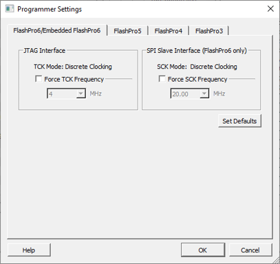
The Programmer Settings dialog box has options for FlashPro6/5/4/3/3X. The following table lists the TCK frequency limitations for the selected programmer:
| Programmer | Limitations |
|---|---|
| FlashPro6 | 1, 2, 3, 4, 5, 6, 7, 8, 9, 10, 11, 12, 13, 14, 15, 16, 17, 18, 19, 20 MHz |
| FlashPro5 | 1, 2, 3, 4, 5, 6, 10, 15, 30 MHz |
| FlashPro4 | 1, 2, 3, 4, 5, 6 MHz |
| FlashPro3/3X | 1, 2, 3, 4, 6 MHz |
For information about TCK frequency limits by target device, see the target device datasheet.
During execution, the frequency set by the FREQUENCY statement in the Program-Debug Data Base (PDB)/Standard Test and Programming Language (STAPL) file overrides the TCK frequency setting in the Programmer Settings dialog box. To prevent this override, check Force TCK Frequency
- 1.00 MHz
- 2.00 MHz
- 2.50 MHz
- 3.33 MHz
- 4.00 MHz
- 5.00 MHz
- 6.67 MHz
- 8.00 MHz
- 10.00 MHz
- 13.33 MHz
- 20.00 MHz
5.7.2.1 FlashPro5/4/3/3X Programmer Settings
(Ask a Question)By default, Force TCK Frequency is not checked. This setting instructs the FlashPro5/4/3/3X to use the TCK frequency specified by the Frequency statement in the PDB/STAPL file(s). If you check Force TCK Frequency, select the appropriate MHz frequency.
For FlashPro4/3X settings, you can switch the TCK mode between Free Running Clock and Discrete Clocking. By default, TCK Mode is set to Free Running Clock. Use Discrete Clocking when there is a JTAG non-compliant device in a chain with Microchip devices.
After you make your selections, click OK.
5.7.2.2 TCK Setting (Force TCK Frequency)
(Ask a Question)If Force TCK Frequency is checked in Programmer Setting, the selected TCK value is set for the programmer and the Frequency statement in the PDB/STAPL file is ignored.
5.7.2.3 Default TCK Frequency
(Ask a Question)If the IPD/STAPL file or Chain does not exist, the default TCK frequency is set to 4 MHz. If more
than one Microchip flash device is targeted in the chain, the
FlashPro Express software passes through all the files and
searches for the freq keyword and the MAX_FREQ
Note field. The FlashPro
Express software uses the lowest value of all the TCK frequency
settings and the MAX_FREQ Note field
values.
5.7.3 Working with Local and Remote Programmers
(Ask a Question)Libero® SoC supports programming Microchip® FPGAs by connecting multiple programmers to your computer. Additionally, you can program Microchip FPGAs over a network without requiring the programmer hardware to be physically connected to your local computer. When a programmer is connected to a remote machine, you can reserve and use it from your local machine as if it were attached locally.
In Libero SoC, new functionality is added in the dialog box.
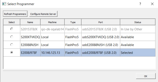
- Refresh Programmers: Requests all available programmers from each connected host, including programmers connected directly to your workstation.
- Configure Remote Server: Opens the Configure Remote Server dialog box, which allows you to add and manage connections to remote programmer server hosts.
- Select: Selects the programmer to use.
- Name: Displays the programmer name.
- Machine: Displays the host name or IP address of the machine to which the programmer is connected. If the programmer is directly connected to your workstation, this field shows Local.
- Type: Specifies the programmer model.
- Port: Specifies the hardware port identifier (USB or COM) on the host machine to which the programmer is connected.
- Status: Indicates the current programmer availability: Available, Selected or In Use by Other.
5.7.4 Configuring and Managing Remote Servers
(Ask a Question)The Configure Remote Server dialog box allows you to connect to remote programmer server hosts and select a programmer from any connected host.
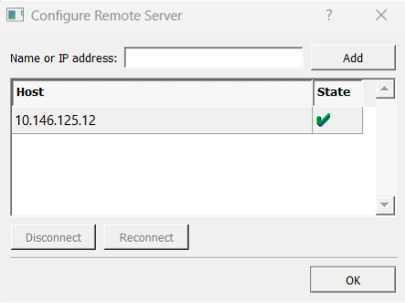
- Name or IP address: Specifies the name or IP address of the remote programmer server to connect to.
- Add: Connects to the server specified in the Name or IP address field and adds it to the Host list.
- Host: Displays the name or IP address of each remote server you have added.
- State: Indicates the connection status of the remote server. A green check mark confirms a successful connection. A red cross indicates that the connection has failed.
- Disconnect: Releases all reserved programmers and disconnects from the selected host.
- Reconnect: Reconnects to a host that has a failed connection.
- OK: Reserves the selected programmer, making it unavailable to other users, and releases all other programmers. Closes the Configure Remote Server dialog box.
5.7.5 Remote Programming Server (RPS) Installation Instructions
(Ask a Question)You can make your local machine act as a remote server. This allows other users within the same network to use FlashPro programmers physically connected to it.
The RPS is installed directly with the Libero® SoC Media Installer. Complete the following instructions in the Libero SoC Setup wizard:- Follow the instructions in the wizard from the Welcome to Installation Folder windows.
- In the Select Installation Type window, choose the Custom option.
- In the Select Components window, with other desired components, select the RPS checkbox to include the functionality in the installer.
- In the RPS Server Configuration window, specify the
desired port numbers for programming requests.
- The default ports to accept external connections are 57606 and 57605, which can be changed based on your requirements. These ports must be permitted through the firewall to enable remote access. The Media Installer completes this step for you during the installation.
5.7.6 Remote Programmer Troubleshooting
(Ask a Question)To recover from connection, detection, or reservation problems in Remote Programmer functionality, follow the instructions in this section to verify network connectivity, confirm the programming server is running on the remote machine, and resolve any remaining application issues.
5.7.6.1 Configuring Network Ports
(Ask a Question)- AlmaLinux OS/Red Hat® Linux®:
- Open the terminal.
- Run the following
command:
sudo firewall-cmd --permanent --add-port
              57605-57606/tcp
- Ubuntu:
- Open the terminal.
- Run the following command:
sudo ufw allow 57605:57606/tcp
- Windows® OS:
- From the Start Menu, search for Windows Defender Firewall with Advanced Security, right-click, and select Run as administrator.
- Click Inbound Rules, then click New Rule.
- In the New Inbound Rule Wizard, you are prompted to select the type of rule you want to create. Choose Port to specify that this rule controls traffic based on network port numbers, and click Next.
- Select TCP as the protocol, since the remote programmer requires TCP communication.
- Select Specific local
ports and enter
57605, 57606to limit TCP communication access to theses two ports. Click Next. - Select Allow the connection and click Next.
- Select all three network profile options: Domain, Private, and Public. This ensures that the rule is active regardless of the type of network your computer is connected to. Click Next.
- Enter a name for the rule and click Finish.
5.7.6.2 Configuring the RPS
(Ask a Question)When the remote server is reachable on the network but no programmers are detected, refer to the Libero® SoC Media Installer to verify the post-installation checks.
If the issue has not been resolved, uninstall the RPS from the Media Installer and install again.
5.7.6.3 Application Issues
(Ask a Question)In critical cases where normal behavior cannot be achieved, run the script in administrative mode from the bin folder to clean up any stuck processes and memory.
In case of a critical crash and abnormal behavior from the remote programmer functionality,
run the bin/CleanUpRPS script in the RPS's bin folder or command shell.
- Linux®: Enter the
rm /dev/shm/*command. - Windows® OS: Navigate to the C:/ProgramData/boost_interprocess/ folder and remove all the content.
- Unified Solution: Depending on your operating system, complete the following steps:
- Find the following processes:
prgsrvdmnprgservappdbgservapp
- Kill all the processes.
Locally Connected Programmer Not Detected in Windows® OS
If everything appears to be working but your locally connected programmer is still not recognized, your antivirus or firewall may be blocking the programming software from operating correctly. To resolve this issue, follow these steps to add exceptions for the required applications:
- Open the command prompt as administrator.
- Enter each of the following commands
one at a time with the correct installation path. Press the Enter key after entering
each
command:
New-NetFirewallRule -DisplayName "Programming and Debug Server" -Direction Inbound -Program "<installation path>\Libero_SoC_<version>\Libero_SoC\Designer\bin\prgsrvdmn.exe" -Action AllowNew-NetFirewallRule -DisplayName "Programming Server" -Direction Inbound -Program "<installation path>\Libero_SoC_<version>\Libero_SoC\Designer\bin\prgservapp.exe" -Action AllowNew-NetFirewallRule -DisplayName "Debug Server" -Direction Inbound -Program "<installation path>\Libero_SoC_<version>\Libero_SoC\Designer\bin\dbgservapp.exe" -Action Allow