
16.1.5 Special
(Ask a Question)16.1.5.1 APBM
(Ask a Question)The APBM macro is a post-layout APB master macro that provides APB master interface signals for both simulation and post-layout connectivity. It drives APB control, address, write-data, clock and reset outputs, and receives APB slave response, read-data, error, ready and interrupt inputs.
This macro has the following input/output ports. These are generally asserted after the specified time that is passed as parameters.
| Port Name | Direction | Width | Description |
|---|---|---|---|
| PRESETN | Output | 1 | Active‑low APB reset output driven by the APB master. |
| PSEL | Output | 1 | APB slave select signal. It indicates the selection phase of an APB transfer. |
| PENABLE | Output | 1 | APB enable signal. It is asserted during the enable phase of an APB transfer. |
| PWRITE | Output | 1 | APB write control signal. It is high for write transfers and low for read transfers. |
| PSTRB[3:0] | Output | 4 | APB write strobe signal. It indicates valid byte lanes during write transfers. |
| PADDR[28:0] | Output | 29 | APB address bus. It specifies the address for the APB transaction. |
| PWDATA[31:0] | Output | 32 | APB write data bus. It carries data during APB write transfers. |
| PSELFAST | Output | 1 | Fast slave select signal. It is used for optimization or early APB selection. |
| PSTRBCLK | Output | 1 | This clock is used to qualify or latch APB write strobe signals. |
| PRDATA[31:0] | Input | 32 | APB read data bus. It is returned by the selected slave. |
| PREADY | Input | 1 | APB ready signal. It indicates the completion of the APB transfer. |
| PSLVERR | Input | 1 | APB slave error indicator. It is asserted on a transfer failure. |
| PINTERRUPT | Input | 1 | This interrupts the input from APB slave to the APB master. |
| PCLK | Output | 1 | APB clock output signal. |
16.1.5.2 BANKEN
(Ask a Question)The BANKEN macro is a post-layout bank-enable macro that asserts a bank enable signal after a programmable delay, allowing the associated I/O or HSIO bank to be enabled during simulation or post-layout operation.
This macro has only one input/output port. It is generally asserted after the specified time that is passed as parameters.
| Port Name | Direction | Width | Description |
|---|---|---|---|
| BANK_EN | Output | 1 | Bank-enabled output signal. It is asserted high after a programmable simulation delay to enable the associated IO/HSIO bank. |
The following table lists the parameters and their descriptions that are used to configure the functionalities of the macro.
| Name | Width | Description |
|---|---|---|
| BANK_EN_SIMULATION_DELAY | Real / Integer | Simulation delay before BANK_EN is asserted high after initialization. |
| BANK_NUMBER | Integer | Identifies the bank number associated with this enable signal. |
16.1.5.3 BANKCTRL_GPIO
(Ask a Question)The BANKCTRL_GPIO macro is a post-layout GPIO bank calibration-control macro. It provides calibration status and interrupt indication and accepts control inputs to start, load, lock and adjust GPIO bank calibration codes.
This macro has the following input/output ports. These are generally asserted after the specified time that is passed as parameters.
| Port Name | Direction | Width | Description |
|---|---|---|---|
| CALIB_STATUS | Output | 1 | Calibration status output. It is asserted high when the GPIO bank calibration is complete and/or locked. And, it is de-asserted when the calibration is in progress. |
| CALIB_INTERRUPT | Output | 1 | Calibration completion interrupt signal. It pulses high to indicate the end of the calibration sequence. |
| CALIB_DIRECTION | Input | 1 | It selects the direction of calibration code adjustment during calibration operations. |
| CALIB_LOAD | Input | 1 | It loads new calibration codes into the IO bank. It must be asserted only when CALIB_STATUS is high. |
| CALIB_LOCK | Input | 1 | It locks the calibrated values. When asserted, calibration is considered complete, and CALIB_STATUS is asserted. |
| CALIB_MOVE_NCODE | Input | 1 | It requests adjustment (movement) of the N‑side calibration code. |
| CALIB_MOVE_PCODE | Input | 1 | It requests adjustment (movement) of the P‑side calibration code. |
| CALIB_START | Input | 1 | It starts the calibration process, clears CALIB_STATUS and initiates calibration. |
| CALIB_MOVE_DIFFR_PVT | Input | 1 | It requests movement of the differential PVT calibration code. |
The following table lists the parameters and their descriptions that are used to configure the functionalities of the macro.
| Name | Width | Description |
|---|---|---|
| PC_REG_CALIB_SOFTRESET | 1 | It enables soft reset for the calibration logic. |
| PC_REG_CALIB_PCODE | 6 | Initial P‑side calibration code value |
| PC_REG_CALIB_NCODE | 6 | Initial N‑side calibration code value |
| PC_REG_CALIB_TRIM | 1 | It enables trimming during calibration. |
| PC_REG_CALIB_START | 1 | Default calibration start control value |
| PC_REG_CALIB_LOCK | 1 | Default calibration lock control value |
| PC_REG_CALIB_LOAD | 1 | Default calibration load control value |
| PC_REG_CALIB_DIR | 1 | Default calibration direction control |
| PC_REG_CALIB_MOVE_PCODE | 1 | Default enable for P‑side calibration code movement |
| PC_REG_CALIB_MOVE_NCODE | 1 | Default enable for N‑side calibration code movement |
| PC_REG_CALIB_DIFFR | 4 | Initial differential calibration code value |
| PC_CALIB_MOVE_DIFF | 1 | It enables movement of differential calibration code. |
| PC_CALIB_D_OFFSET | 4 | Differential calibration offset value |
| PC_CALIB_D_OFFSET_DIRECTION | 1 | Direction control for differential offset adjustment |
| PC_CALIB_N_OFFSET | 6 | N‑side calibration offset value |
| PC_CALIB_N_OFFSET_DIRECTION | 1 | Direction control for N‑side offset adjustment |
| PC_CALIB_P_OFFSET | 6 | P‑side calibration offset value |
| PC_CALIB_P_OFFSET_DIRECTION | 1 | Direction control for P‑side offset adjustment |
| PC_REG_DIFFR_VSEL | 2 | Differential voltage select for calibration |
| BANK_NUMBER | Integer | It identifies the GPIO bank number for this instance. |
| CALIB_STATUS_SIMULATION_DELAY | Integer | Simulation delay before CALIB_STATUS is asserted after initialization |
| CALIB_CALIB_INTERRUPT_DELAY | Integer | Simulation delay used to generate the calibration interrupt pulse |
16.1.5.4 BANKCTRL_HSIO
(Ask a Question)The BANKCTRL_HSIO macro is a post-layout HSIO bank calibration-control macro. It provides calibration status and interrupt indication and accepts control inputs to manage HSIO calibration, including P/N code and slew-rate calibration adjustments.
This macro has the following input/output ports. These are generally asserted after the specified time that is passed as parameters.
| Name | Direction | Width | Description |
|---|---|---|---|
| CALIB_STATUS | Output | 1 | Calibration status output. It is asserted high when HSIO bank calibration is complete and/or locked. It is de-asserted while calibration is in progress. |
| CALIB_INTERRUPT | Output | 1 | Calibration completion interrupt signal. It pulses high after calibration finishes. |
| CALIB_DIRECTION | Input | 1 | It selects the direction of calibration code adjustment. |
| CALIB_LOAD | Input | 1 | It loads new calibration codes into the HSIO bank. It must only be asserted when CALIB_STATUS is high. |
| CALIB_LOCK | Input | 1 | It locks the calibrated values and when asserted, CALIB_STATUS is set high. |
| CALIB_MOVE_NCODE | Input | 1 | It requests the movement (adjustment) of the N‑side calibration code. |
| CALIB_MOVE_PCODE | Input | 1 | It requests the movement (adjustment) of the P‑side calibration code. |
| CALIB_START | Input | 1 | It starts the calibration process, clears CALIB_STATUS and initiates the calibration. |
| CALIB_MOVE_SLEWR | Input | 1 | It requests the movement (adjustment) of the slew‑rate rise calibration code. |
| CALIB_MOVE_SLEWF | Input | 1 | It requests the movement (adjustment) of the slew‑rate fall calibration code. |
The following table lists the parameters and their descriptions that are used to configure the functionalities of the macro.
| Name | Width | Description |
|---|---|---|
| PC_REG_CALIB_SOFTRESET | 1 | It enables soft reset for the HSIO calibration logic. |
| PC_REG_CALIB_PCODE | 6 | Initial P‑side calibration code value |
| PC_REG_CALIB_NCODE | 6 | Initial N‑side calibration code value |
| PC_REG_CALIB_TRIM | 1 | It enables trimming during calibration. |
| PC_REG_CALIB_START | 1 | Default calibration start control value |
| PC_REG_CALIB_LOCK | 1 | Default calibration lock control value |
| PC_REG_CALIB_LOAD | 1 | Default calibration load control value |
| PC_REG_CALIB_DIR | 1 | Default calibration direction control |
| PC_REG_CALIB_MOVE_PCODE | 1 | Default enable for P‑side calibration code movement |
| PC_REG_CALIB_MOVE_NCODE | 1 | Default enable for N‑side calibration code movement |
| PC_CALIB_N_OFFSET | 6 | N‑side calibration offset value |
| PC_CALIB_N_OFFSET_DIRECTION | 1 | Direction control for N‑side offset adjustment |
| PC_CALIB_P_OFFSET | 6 | P‑side calibration offset value |
| PC_CALIB_P_OFFSET_DIRECTION | 1 | Direction control for P‑side offset adjustment |
| PC_SLEWR | 6 | Initial slew‑rate rise control code |
| PC_SLEWF | 6 | Initial slew‑rate fall control code |
| PC_CALIB_ROFFSET | 6 | Slew‑rate rise calibration offset value |
| PC_CALIB_FOFFSET | 6 | Slew‑rate fall calibration offset value |
| PC_CALIB_ROFFSET_DIR | 1 | Direction control for slew‑rate rise offset adjustment |
| PC_CALIB_FOFFSET_DIR | 1 | Direction control for slew‑rate fall offset adjustment |
| PC_CALIB_MOVE_SLEWR | 1 | It enables the movement of slew‑rate rise calibration code. |
| PC_CALIB_MOVE_SLEWF | 1 | It enables the movement of slew‑rate fall calibration code. |
| BANK_NUMBER | Integer | It identifies the HSIO bank number for this instance. |
| CALIB_STATUS_SIMULATION_DELAY | Integer | Simulation delay before CALIB_STATUS is asserted after initialization |
| CALIB_CALIB_INTERRUPT_DELAY | Integer | Simulation delay used to generate the calibration interrupt pulse |
16.1.5.5 FCEND_BUFF
(Ask a Question)| Input | Output |
|---|---|
| A | Y |
| A | Y |
|---|---|
| 0 | 0 |
| 1 | 1 |
16.1.5.6 FCINIT_BUFF
(Ask a Question)| Input | Output |
|---|---|
| A | Y |
| A | Y |
|---|---|
| 0 | 0 |
| 1 | 1 |
16.1.5.7 PF_SPI
(Ask a Question)| Port | Direction | Polarity | Description |
|---|---|---|---|
| D_I | Output | — | This port is connected to the SPI DI pin. |
| FAB_SPI_OWNER | Output | High | Indicator to the Fabric SPI-Initiator if the SPI Port is available. |
| CLK_OE | Input | High | Enables the SPI CLK output. |
| CLK_O | Input | — | This port drives the SPI Clock pin. CLK_OE must be HIGH to drive. |
| D_OE | Input | High | Enables the Data output. |
| D_O | Input | — | This port drives the SPI DO pin. D_OE must be HIGH to drive. |
| SS_OE | Input | High | Enables the Target Select output. |
| SS_O | Input | High | This port drives the SPI Target Select (SS) pin. SS_OE must be HIGH to drive. |
| CLK | Output | — | SPI Clock output pin. |
| DI | Input | — | SPI Serial Data input pin. |
| DO | Output | — | SPI Serial Data output pin. |
| SS | Output | High | SPI Target Select output pin. |
| IFACE | Input | High | This port is mapped to the IO_CFG_INTF pin. This pin must be tied to high together with the SC_SPI_EN pin to enable SPI port for the fabric macro to work. |
| FLASH | Input | High | This port is mapped to the SC_SPI_EN pin. This pin must be tied to high together with the IO_CFG_INTF pin to enable the SPI port for fabric macro to work. |
16.1.5.8 SC_STATUS
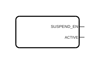
(Ask a Question)SC_STATUS macro, the SUSPEND_EN
signal indicates that the device is in avionics mode, also known as system controller
suspend mode, meaning device initialization is complete and all hardware defaults are
set.- At simulation time t = 0, set
SUSPEND_EN= 0, andACTIVE= 1. - At 0.625 µs after the later
assertion of
DEVICE_INIT_DONE= 1 orAUTOCALIB_DONE= 1, setSUSPEND_EN= 1, andACTIVE= 0 to indicate that the System Controller has entered Suspend mode.
Value of
SUSPEND_EN | Description |
|---|---|
| 0 | The device is not in System Controller Suspend mode. |
| 1 | The device is in System Controller Suspend mode. |
| Port | Width | Direction | Description |
|---|---|---|---|
| SUSPEND_EN | 1 | Output | Asserted when the System Controller is in Suspend mode. |
| ACTIVE | 1 | Output | Asserted when the System Controller is in Active mode. |
The System Controller Suspend mode works as follows:
- When JTAG_TRST_B is asserted low:
- SUSPEND_EN is asserted high.
- ACTIVE is asserted low.
- When JTAG_TRST_B is asserted high:
- SUSPEND_EN is asserted low.
- ACTIVE is asserted high when the System Controller is actively performing a function.
The following table shows the states when the System Controller has finished its operations and entered Suspend mode, not just when the Suspend mode setting is enabled.
| Port | Direction | Suspend Mode Enabled | Suspend Mode Disabled |
|---|---|---|---|
| SUSPEND_EN | OUTPUT | 1 | 0 |
| ACTIVE | OUTPUT | 0 | 1: when the System Controller is actively performing a function. |
Before performing operations that require the System Controller, such as programming or debugging, ensure the device is not in Suspend mode.
16.1.5.9 OSC_RC160MHZ
(Ask a Question)The OSC_RC160MHZ oscillator is an RC oscillator that provides a free-running clock of 160 MHz at CLK when OSC_160MHZ_ON is tied HIGH.
16.1.5.10 OSC_RC2MHZ
(Ask a Question)The OSC_RC2MHZ oscillator is an RC oscillator that provides a free-running clock of 2 MHz at CLK when OSC_2MHZ_ON is tied HIGH.
16.1.5.11 LIVE_PROBE_A
(Ask a Question)This is one of the specialized probes. SmartDebug uses the dedicated and specialized probe points built in the FPGA fabric, which significantly accelerates and simplifies the debug process.
16.1.5.12 INIT
(Ask a Question)| Port Name | Direction | Width | Description |
|---|---|---|---|
| FABRIC_POR_N | Output | 1 | Active‑low power‑on reset for the fabric. It is asserted after the fabric initialization delay and can be de-asserted when the fabric is operational. |
| PCIE_INIT_DONE | Output | 1 | Indicates PCIe initialization has completed. It is used by fabric logic to hold PCIe-related fabric logic in reset until the PCIe controller is initialized. It is asserted after initializing the PCIe lane instances placed in the PCIe quad. If only XCVR lanes are placed in the PCIe quad, only XCVR_INIT_DONE is asserted. |
| RFU[0] | Asserted when the XCVR (high‑speed transceiver) block initialization is completed. | ||
| RFU[1] | Asserted when μSRAM is initialized from sNVM. | ||
| RFU[2] | Asserted when μSRAM is initialized from µPROM. | ||
| RFU[3] | Asserted when μSRAM is initialized from SPI flash. | ||
| RFU[4] | Asserted when SRAM is initialized from sNVM. | ||
| RFU[5] | Asserted when SRAM is initialized from µPROM. | ||
| RFU[6] | Asserted when SRAM is initialized from SPI flash. | ||
| RFU[7] | Asserted when auto calibration is done. It is reserved for future use. | ||
| RFU[8] | Reserved for future use. | ||
| RFU[9] | Reserved for future use. | ||
| RFU[10] | Reserved for future use. | ||
| RFU[11] | Asserted when automatic IO calibration is complete. | ||
| RFU[11:0] | Output | 12 | Reserved‑for‑future‑use status outputs. It is driven high after programmed initialization delays. |
| SRAM_INIT_DONE | Output | 1 | Indicates on‑chip SRAM initialization has completed. It is asserted when the LSRAM blocks are initialized. |
| USRAM_INIT_DONE | Output | 1 | Indicates user SRAM initialization has completed. It is asserted when the µSRAM blocks are initialized. |
| GPIO_ACTIVE | Indicates GPIO subsystem is active and ready. This signal can be used by user logic to determine if the calibration completes for each I/O banks. # denotes the bank number (0,1, 7, 8, and 9). | ||
| HSIO_ACTIVE | Indicates HSIO subsystem is active and ready. This signal can be used to monitor if there is VDDI power loss on specific I/O banks. This is an output signal from the INIT_MONITOR IP if any of the corresponding bank is selected. # denotes the bank number (0,1, 7, 8, and 9). | ||
| UIC_INIT_DONE | Output | 1 | Indicates UIC (device‑level) initialization has completed. |
The following table lists the parameters and their descriptions that are used to configure the functionalities of the macro.
| Name | Width | Description |
|---|---|---|
| FABRIC_POR_N_SIMULATION_DELAY | Real / Integer | Simulation delay before FABRIC_POR_N is asserted. |
| GPIO_ACTIVE_SIMULATION_DELAY | Real / Integer | Simulation delay before GPIO_ACTIVE is asserted. |
| HSIO_ACTIVE_SIMULATION_DELAY | Real / Integer | Simulation delay before HSIO_ACTIVE is asserted. |
| PCIE_INIT_DONE_SIMULATION_DELAY | Integer | Simulation delay before PCIE_INIT_DONE is asserted. |
| RFU_SIMULATION_DELAY | Real / Integer | Simulation delay for RFU outputs (legacy, not used). |
| SRAM_INIT_DONE_SIMULATION_DELAY | Integer | Simulation delay before SRAM_INIT_DONE is asserted. |
| UIC_INIT_DONE_SIMULATION_DELAY | Integer | Simulation delay before UIC_INIT_DONE is asserted. |
| USRAM_INIT_DONE_SIMULATION_DELAY | Integer | Simulation delay before USRAM_INIT_DONE is asserted. |
| SUSPEND_MODE | 1 | Enables suspend behavior; when set, all INIT outputs are de-asserted after initialization. |
16.1.5.13 PFSOC_SCSM
(Ask a Question)The PFSOC_SCSM macro allows a PolarFire SoC device, configured with the
System Controller Suspend Mode (SCSM) enabled, to support MSS reboots during normal
device operation. Without this macro, the System Controller:
- Will remain in suspend mode during normal operation after the initial power-up device initialization and MSS boot completion.
- Will not service subsequent MSS boot requests, even if you reset the MSS.
You must connect the REBOOT_REQUESTED_M2F output of the MSS component to
the SC_WAKE input pin of the PFSOC_SCSM macro. Other
connections are not permitted.
REBOOT_REQUESTED_M2F port in the MSS configurator, check the
Expose Feedback ports to Fabric option under the
Misc tab.With this connection added to your FPGA fabric design, whenever the MSS
REBOOT_REQUESTED_M2F output is asserted, the System Controller exits SCSM
and processes the pending MSS reboot request. Once the MSS boots, the
REBOOT_REQUESTED_M2F output will deassert and the System Controller
returns to the suspend mode. The System Controller status can be monitored via the
SC_STATUS macro.
PFSOC_SCSM macro only
supports the PolarFire SoC (production device) family. PolarFire SoC Engineering Silicon
(ES) devices are not supported.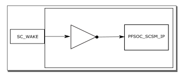
Design Rule Checks
Following are the Design Rule Checks (DRCs) for the PFSOC_SCSM
macro.
- Check that the driver is only
MSS REBOOT_REQUESTED_M2F, otherwise thePFSOC_SCSMmacro will error out and stop the flow with the following message:The PFSOC_SCSM primitive macro only supports being driven by the MSS component’s REBOOT_REQUESTED_M2F output. Other drivers are not supported. See the PolarFire SoC Macro Library Guide for more information. - If Suspend is not enabled, and
the
PFSOC_SCSMis instantiated, a warning is issued in the Export Design Initialization Data and Memory Report file.The PFSOC_SCSM macro is instantiated in the design, but System Controller Suspend Mode is not enabled. This macro is intended for use with System Controller Suspend Mode. See the PolarFire SoC Macro Library Guide for more information. - If Suspend is enabled, and the
MSS is used, but the
PFSOC_SCSMmacro is not instantiated, a warning is issued in the Export Design Initialization Data and Memory Report file.The PFSOC_SCSM macro is not instantiated even though System Controller Suspend Mode is enabled and the MSS component is instantiated. The system controller will not be available to process MSS reboot requests during operation. See the PolarFire SoC Macro Library Guide for more information. - The
PFSOC_SCSMmacro is visible only for the PolarFire SoC designs. This macro is required for the PolarFire SoC designs using the MSS component and for enabling System Controller Suspend Mode (SCSM). When not used in the PolarFire SoC designs, Libero ties the input to the System Controller to a static1. - If an ES device or a PolarFire
family is selected, the
PFSOC_SCSMmacro will error out and stop the flow in compile with the following error message, as only production PolarFire SoC devices are supported.CMPPF_026: This design has one or more instances of the PFSOC_SCSM macro which is not supported for the device in use. Before compiling, this macro(s) must be removed from the design. - For RT PolarFire SoC
devices:
Error: ThePFSOC_SCSMpin cannot be static. Refer to the PolarFire SoC Macro Library Guide for more information."