
1.5.2.1 PIC32CXMTG-EK
The following picture shows the PIC32CXMTG-EK board connected with PL460-EK and REB215-XPRO expansion boards.

PL460-EK is connected to XPRO Interface connector (J10) of PIC32CXMTG-EK. A 15V DC jack must be plugged into PL460-EK in order to supply the power for PLC transmission. For additional information about PL460-EK, refer to the user guide.
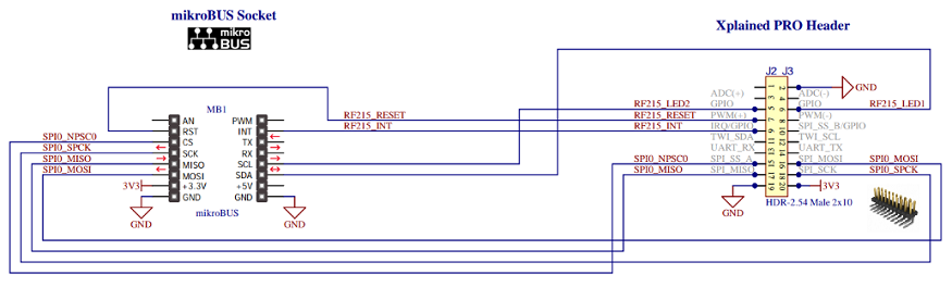
REB215-XPRO is connected to mikroBUS 1 connector (J8) of PIC32CXMTG-EK using a mikroBUS to REB215 adapter (schematic shown below). For additional information about REB215-XPRO, refer to the user guide.
It is possible to connect only one expansion board and the application runs correctly, with only PLC or RF interface available.
- See Application information messages on Console. UART baud-rate is configured at 115200 bps (it cannot be higher due to hardware limitations on this board).
- Flash/debug the PIC32CXMTG device with the on-board J-Link debugger
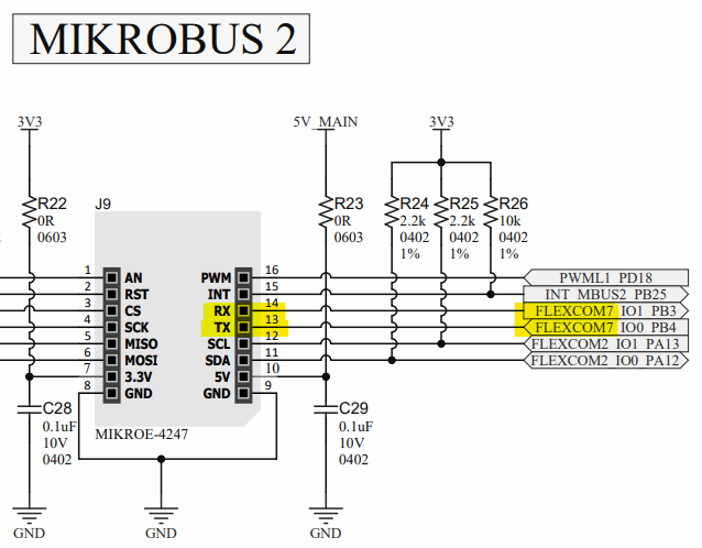
The connection for the PRIME API serialization is done through mikroBUS 2 connector, where USART7 is mapped.
The following figure shows the connection between modem and PC.

For additional information about PIC32CXMTG-EK, refer to the user guide.