1.4.1 Application Example
Microchip PHY PLC & Go application is a point to multi-point chat application built on top of the state-of-the-art PHY layer of G3-PLC protocol.
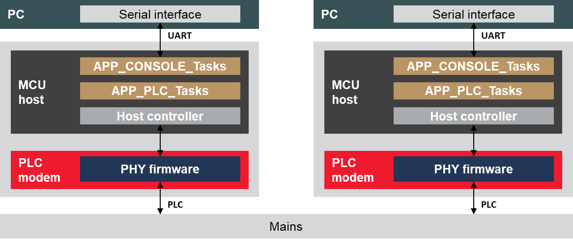
This application example assumes that a host device (a PC, for example) is connected through a serial interface (UART, USB) to a Microchip evaluation kit acting as a PLC modem.
The figure below shows a block diagram of the PHY PLC & Go application.

- Baud-rate depending on the platform, see 1.4.3 Hardware Configuration
- 8 data bits
- no parity
- 1 stop bit
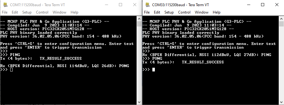
When the terminal emulator is connected to the serial port and the first character is entered by the user, the PLC & Go application shows in the console some information about the hardware platform and the firmware running, and it waits for a PLC message to be sent/received or configuration request. The PLC message is sent when a carriage return character is entered. If the user enters the ASCII character 0x13 (‘CTRL+S’), a configuration menu is shown.
- Configure modulation type and modulation scheme used for transmission
- Configure the frequency band (in case of using a Microchip evaluation board that supports several bands of transmission)
- Enable/disable sleep mode (the STBY pin of the PLC device needs to be physically connected to a GPIO of the MCU host)
In addition, the application provides some information about the transmitted messages (length of the message) and the received messages (modulation type, modulation scheme, signal level and signal quality):

- PLC PHY initialization and configuration functions
- Handlers for received messages, transmission and events
The app_console.c file contains the chat application which communicates with the PC using the serial port.
