1.7.2 MCC Project Configuration
The following figure shows the MCC project graph of G3 Device UDP/ICMPv6 Responder application for PIC32CXMTG-EK:
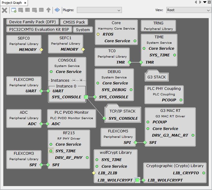
- Since it is an hybrid project, both G3 MAC RT and RF215 drivers are present. For PLC-only or RF-only projects, only one of them is needed.
- The PLC PVDD Monitor service is needed to monitor the PVDD voltage of PL460 in order to disable PLC transmission in case the voltage is not in the expected range, to avoid PL460 damage. If the PVDD voltage is in the expected range the PLC transmission is enabled.
- The PLC PHY Coupling service is needed to configure the PLC transmission parameters for the selected transmission coupling branch.
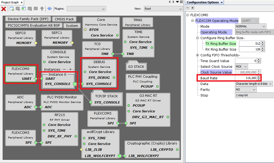
- The Console and Debug system services are used to show debug information through the serial interface.
- The Time system service is required by both G3 MAC RT and RF215 drivers. It is also used by the application to create timers.
- The TRNG peripheral library is used by the Random service to generate random numbers, which is needed by the G3 stack. It is not mandatory because the Random service can generate random numbers without it, but if the MCU used has a TRNG peripheral it is recommended to use it.
- Cryptographic and wolfCrypt libraries are used by the Security service to perform cryptographic operations needed by the G3 stack.
- The G3 STACK folder contains all the components needed by the G3 stack.
- The TCP/IP STACK folder contains all the TCP/IP components used by the application.
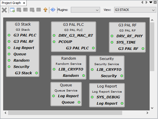
- Since it is an hybrid project, both PLC and RF G3 PALs are present. For PLC-only or RF-only projects, only one of them is needed (G3 Mode of Operation should also be changed in MCC options of G3 Stack).
- Random, Security, Queue and Log Report services are always needed by the G3 stack.
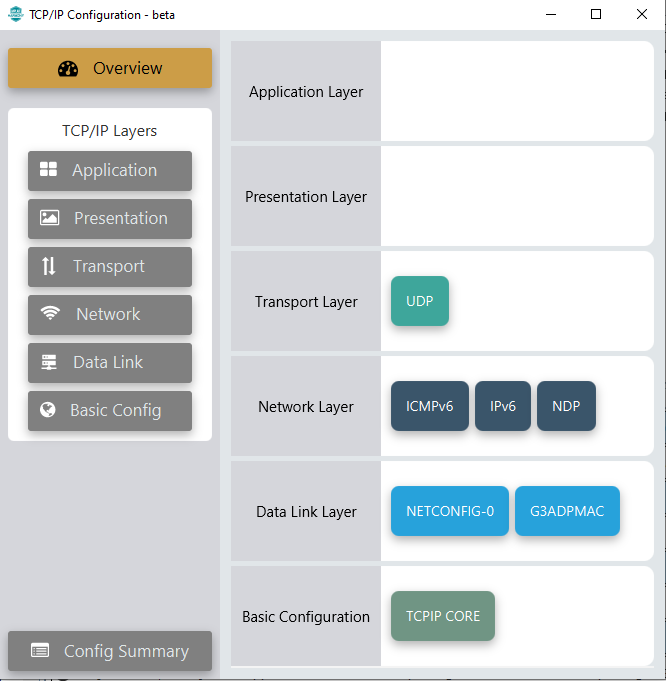
- TCPIP CORE is always needed by the TCP/IP stack.
- In this application there is only one TCP/IP interface (NETCONFIG-0), which is connected to G3ADPMAC. G3ADPMAC is the interface between the TCP/IP stack and the G3 stack API (ADP).
- IPv6 is the layer on top of the G3 stack (ADP).
- NDP (Neighbor Discovery Protocol) module is required by the TCP/IP stack when IPv6 is used.
- ICMPv6 is required by NDP module, and it is also needed to reply to ICMPv6 Echo Request messages (required by the G3 conformance tests).
- UDP is used to implement the UDP responder, required by the G3 conformance tests.
The following figure shows the MCC configuration of the G3 Stack:
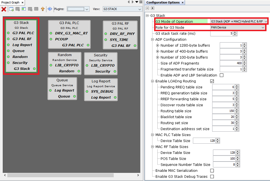
- G3 Mode of Operation: It can be changed if Hybrid PLC & RF is not needed.
- Role for G3 Node: Configured to PAN Device for this application.
- For more information about G3 stack configuration, refer to its documentation (smartenergy_g3 repository).
The following figure shows the MCC configuration of NETCONFIG:
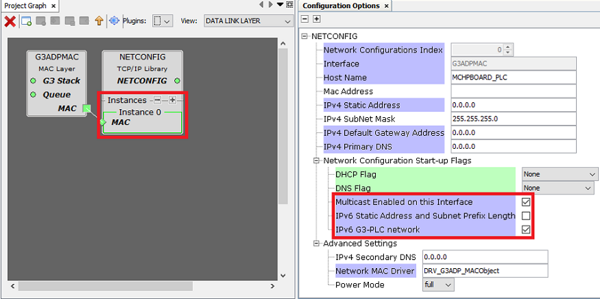
- Multicast Enabled on this Interface: It must be enabled because it is needed for G3 Conformance certification tests. It is automatically enabled by G3ADPMAC component.
- IPv6 Static Address and Subnet Prefix Length: IPv6 address is configured dynamically, depending on G3 PAN ID and Short Address. This option is automatically disabled by G3ADPMAC component.
- IPv6 G3-PLC network: It must be enabled when TCP/IP interface uses the G3 stack (G3ADPMAC). It is automatically enabled by G3ADPMAC component.
- For more information about NETCONFIG configuration, refer to its documentation (net repository).
The following figure shows the MCC configuration of IPv6:
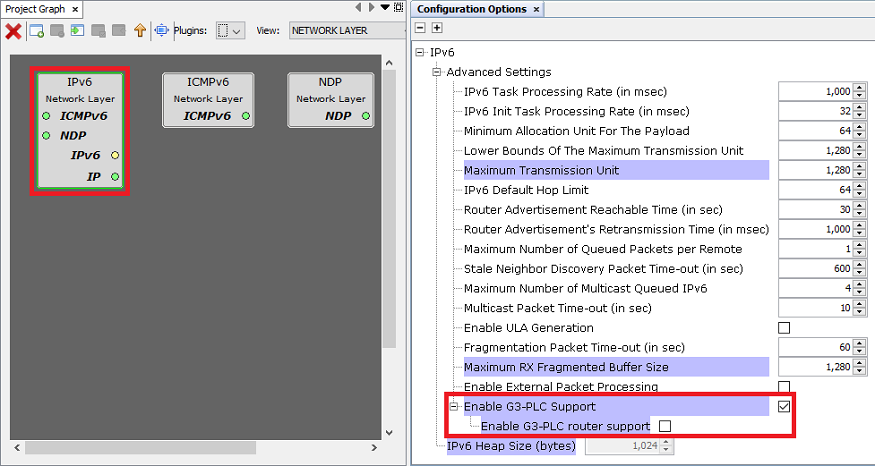
- Enable G3-PLC Support: It must be
enabled when a TCP/IP interface uses the G3 stack (G3ADPMAC). It is automatically
enabled by G3ADPMAC component.
- Enable G3-PLC router support: In this project it is disabled because it is a Device. It is automatically disabled by G3ADPMAC component if G3 Mode of Operation is PAN Device.
- For more information about IPv6 configuration, refer to its documentation (net repository).
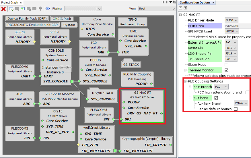
The G3 Device UDP/ICMPv6 Responder application loads by default the configuration to use the default coupling stage of the evaluation kit (Multiband FCC + CENELEC-A for the PL460-EK). If other PLC band configuration is required, it can be easily modified in the MCC options of G3 MAC RT driver, as shown below:
The serial interface used to show debug information is configured in the MCC configuration of Console and Debug services. It can be UART or USB (if the device supports USB).
