
3.1.3.2 Smart Wireless Thermostat BLE central application on PIC32CZ CA90 Curiosity Ultra Development Board
Description
This project employs the RNBD451 BLE module to create multi-link BLE connections with two peripheral nodes. Once connected, the central node functions as a GATT client, periodically requesting real-time temperature data from the peripheral GATT servers(peripherals) and displaying it on a 4.3-inch maXTouch graphics display. Users can set and send temperature threshold limits to the BLE peripheral nodes using the GUI. Furthermore, the central application transmits the gathered temperature data to the WFI32 IoT gateway via UART for real-time monitoring on the AWS cloud.
Modules/Technology Used
-
Peripheral Modules
- EVSYS
- NVMCTRL
- SERCOM 0 (I2C)
- SERCOM 2(USART)
- SERCOM 4 (USART)
- Timers TCC0/TCC1/TCC9
-
Graphics
- EBI
- I2C
- LE LCC
- Legato
- Legato Graphics w/PDA TM430
- Max-Touch Controller
- PDATM4301B
- GFX Core LE
-
System Services
- Time
-
Input
- Input System Service
-
Wireless driver
- RNBD BLE driver
-
BSP
- PIC32CZ CA90 Curiosity Ultra BSP
-
Harmony Core Service


Hardware Used
Software/Tools Used
The projects have been verified to work with the following versions of software tools:
- For Central PIC32CZ_CA90 BLE GATT Client, refer Project Manifest
- MPLAB® X IDEv6.20
- MPLAB® XC32 C/C++ Compilerv4.45
- Python 3.5 or higher.
Because Microchip regularly updates tools, occasionally issue(s) couldbe discovered while using the newer versions of the tools. If theproject doesn’t seem to work and version incompatibility is suspected,it is recommended to double-check and use the same versions that theproject was tested with. To download original version of MPLAB® Harmonyv3 packages, refer to document How to Use the MPLAB® Harmony v3 ProjectManifestFeature (DS90003305)
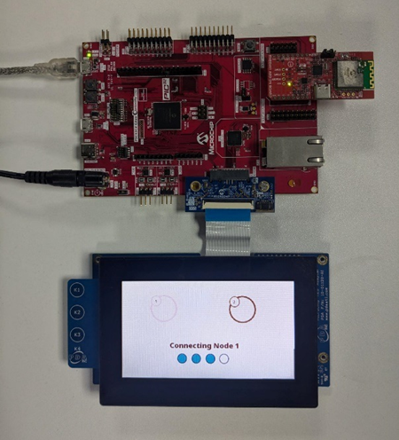
Hardware Setup
PIC32CZ CA90 Thermostat Central Node:
-
Connect the RNBD451 Add-on board to the mikroBUS header on the PIC32CZ CA90 Curiosity Ultra Development Board.
-
Make sure the jumper J2 of the RNBD451 Add-on board has the cap mounted between J(2-1) and J(2-2) to be powered by the mikroBUS header.
-
Connect the 565 LCD Adapter Graphics Card to the "Graphics connector" of the PIC32CZ CA90 Curiosity Ultra Development Board.
-
Connect the 4.3” WQVGA maXTouch Display module to the Graphics interface of the PIC32CZ CA90 Curiosity Ultra Development Board.
-
Connect the jumper wire from pin PC08 on EXT1 for SERCOM UART TX to communicate with the WFI32 IoT board.
-
Connect the PIC32CZ CA90 Curiosity Ultra Development Board to the Host PC as a USB Device through a Type-A male to micro-B USB cable connected to Micro-B USB (Debug USB) port.
-
Power the PIC32CZ CA90 Curiosity Ultra Development Board through the Barrel connector using the wall-mount 9V power supply provided in the kit, or Power supply with any Voltage (6.5-14V DC) and Current (> 750 mA) range.
Programming prebuilt hex file
-
Open MPLAB® X IDE.
-
Close all existing projects in IDE, if any project is opened.
-
Go to File -> Import -> Hex/ELF File.
-
In the "Import Image File" window, Step 1 - Create Prebuilt Project, Click the "Browse" button to select the prebuilt hex file.
-
Select Device as "PIC32CZ8110CA90208"
-
Ensure the proper tool is selected under "Hardware Tool".
-
Click on the "Next" button.
-
In the "Import Image File" window, Step 2 - Select Project Name and Folder, select appropriate project name and folder.
-
Click on the "Finish" button.
-
In MPLAB® X IDE, click on "Make and Program Device" Button. The device gets programmed.
-
Follow the steps in Running the Demo.
Programming/Debugging Application Project
-
Open the project pic32cz_ca90_cult.X in MPLAB® X IDE from pic32cz_ca90_wireless_thermostat/firmware/pic32cz_ca90_cult_wt_central and set as main project.
-
Ensure "PIC32CZ CA90 Curiosity Ultra" is selected as hardware tool to program/debug the application
-
Build the code and program the device by clicking on the "Make and Program Device" button in MPLAB® X IDE tool bar
-
Follow the steps in Running the Demo as below.
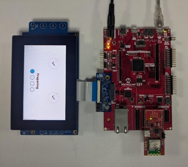
Running the Demo
- Power up the board.
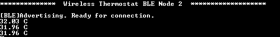
Screen 1: Home Screen
-
The home screen of the demo gets displayed on the Graphics display panel.
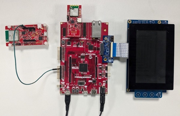
Make sure the BLE peripheral nodes are already programmed with their respective application projects and both the nodes are ready to connect to the central node. The following console message will be displayed after programming the firmware into PIC32CM LS60 Curiosity Pro kit and
WBZ451 Curiosity Development boards in their tera term consoles.
Node 1 Advertising and waiting for connection

Node 2 Advertising and waiting for connection
Note: The pic32cz_ca90_cult.X project does not have any console messages
- Press the “Start” button on the home screen.
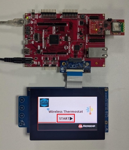
Screen 2: Multi-Connect Screen
-
The central node starts to scan for the peripheral nodes.
“Scanning” appears on the connect screen. Please wait for a few seconds for the BLE scanning process to complete.
-
Once the scanning completes, the central initiates connection with BLE
Node 1.
- Once the peripheral node 1 connects to the central, a tick mark appears on the GUI as below and LED0 is turned on.
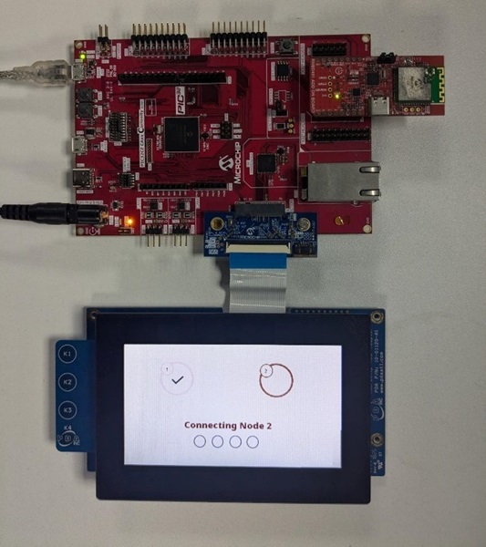
-
Similarly, the central node initiates another connection with BLE sensor node 2.
-
Upon successfully connecting with the second node, a tick mark appears on the GUI and the GUI next screen appears.
-
LED0 and LED1 are turned on with a successful multilink connection on the PIC32CZ CA90 Curiosity Ultra Development Board as below
Screen 3: Multi Node Temperature Monitoring
-
This screen gets updated with node 1 and node 2 temperature data fetched in periodic intervals from the BLE peripheral devices.
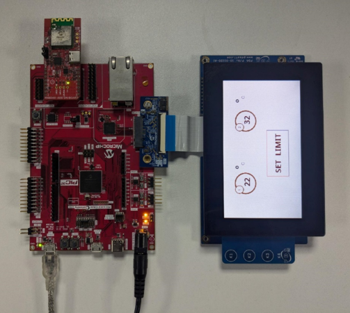
-
Press “Set Limit” button to assign threshold limit for the nodes to cutoff the heating or cooling unit. Once Set Limit is pressed the next screen appears.
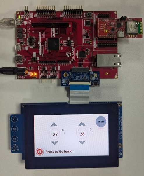
Screen 4: Temperature Control
-
Temperature limits can be set for each of the nodes using the ‘ᴧ’ (Increment) and ‘v’(Decrement) buttons.
-
To set threshold for node 1, adjust the temperature and press “enter”.
-
Similarly, to set threshold for node 2, adjust the temperature for node 2 and press “enter”.
Note: Please note that the limits for each node should be set individually. The nodes do not get updated simultaneously. To set threshold for both the nodes, change the limit in one node, press "enter" and then do the same for the other node.
- Press “Press to Go back” to go to screen 3.
Comments
- Getting Started Extended Application on PIC32CZ CA90 Curiosity Ultra Development Board
- Creating the First Application on PIC32CZ CAx Microcontrollers Using MPLAB® Harmony v3 with MPLAB® Code Configurator (MCC)
- This application demo builds and works out of box by following the
instructions above in Running the Demo section. If there is a need to
enhance or customize this application demo, use the MPLAB® Harmony v3
Software framework. Refer to the links below to set up and build the
applications using MPLAB® Harmony v3.
- How to Setup MPLAB Harmony v3 Software Development Framework
- Video - How to Set up the Tools Required to Get Started with MPLAB® Harmony v3 and MCC
- Create a new MPLAB Harmony v3 project using MCC
- Update and Configure an Existing MHC-based MPLAB Harmony v3 Project to MCC-based Project
- How to Build an Application by Adding a New PLIB, Driver, or Middleware to an Existing MPLAB Harmony v3 Project
Revision
- v1.7.0 - Released demo application