
3 Getting Started with MPLAB X IDE
Using a Curiosity Nano
- In this example you will learn a simple application using an input and an output to blink an LED
- MPLAB X IDE and XC8 compiler is the software used in this example.
- The Curiosity Nano Board is connected to MPLAB X IDE via the on-board USB connector on the embedded debugger. The USB powers the kit and the embedded debugger will enable debugging and programming via the USB.
Workflow
- Launch MPLAB X IDE.
- The page shown in the figure
below will appear when any Curiosity Nano is connected to MPLAB X IDE.
Figure 3-1. Curiosity Nano Kit Window in MPLAB® X 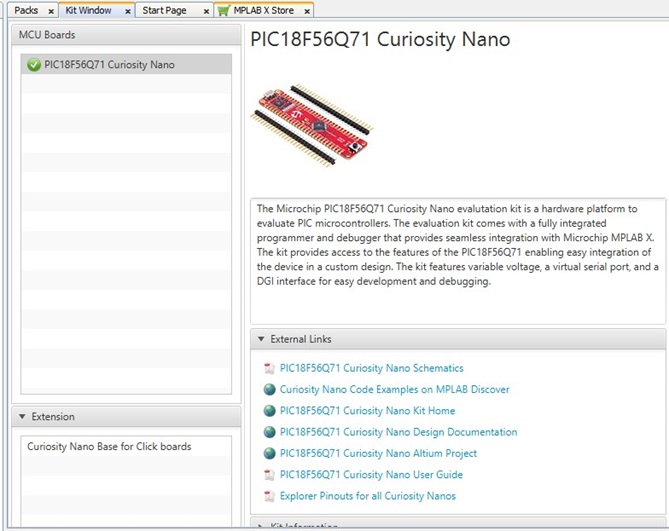
- Start creating a new project by
clicking File→New Project or using the <Ctrl+Shift+N>
shortcut, as shown in Figure 3-2.
Figure 3-2. Create New Project in MPLAB X IDE 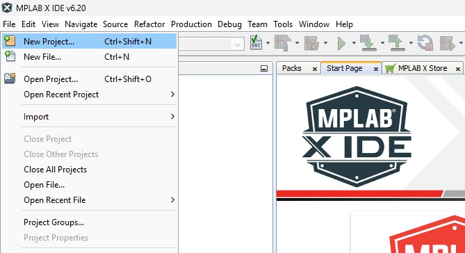
- Select the
Categories→Microchip Embedded and
Projects→Standalone Project template and click
Next.
Figure 3-3. New Project Window 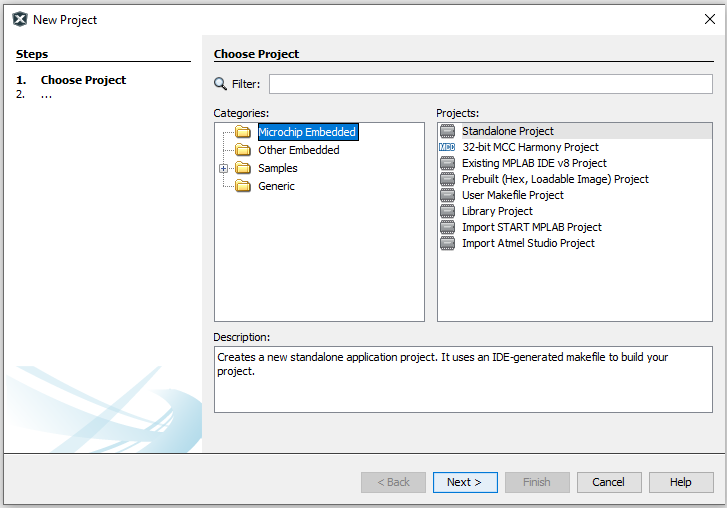
- Select the microcontroller you
are using (e.g., PIC18F56Q71) and click Next, as shown in Figure 3-4.
Figure 3-4. Device Selection Window 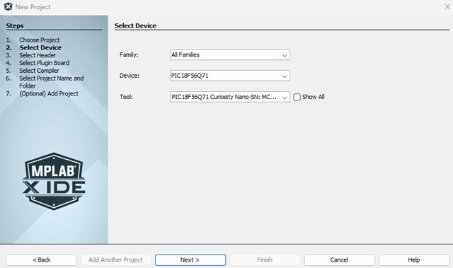
Then select the board and the desired compiler, if there are any.
- Select an available compiler
(e.g., XC8 (v.2.5)) the latest is usually on the top, if needed there is also a
link to (Download Latest) and click Next > to
continue.
Figure 3-5. Compiler Selection Window 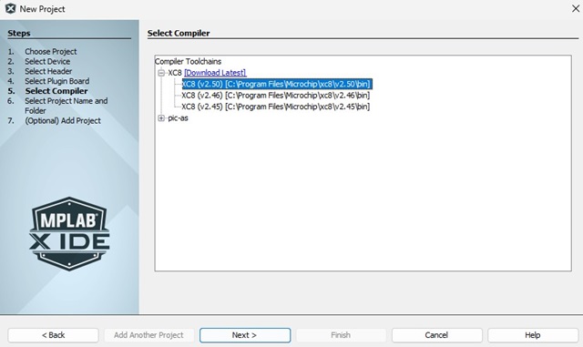
- Type in the Project Name: (e.g.,
LED_TOGGLE) and location (e.g.,
C:\) of the project and click Finish.Figure 3-6. Project Name and Location Selection Window 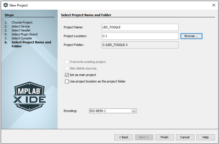
- Create a new
main.cfile by clicking File→New File or using the <Ctrl+N> shortcut.Figure 3-7. Create a New File in MPLAB X 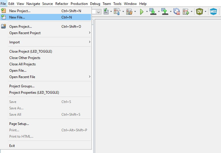
- Select the
Categories→C and File Types→C Main File
template, then click Next, as shown in Figure 3-8.
Figure 3-8. New File Window 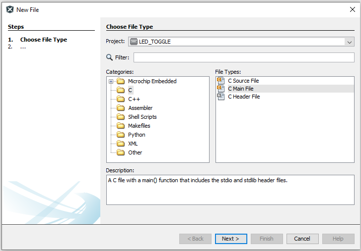
- Type in the file name (e.g.,
main) and click Finish.Figure 3-9. File Name Window 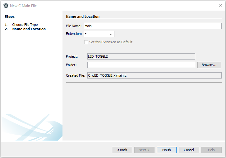
- Replace the
main.cfile with the following code snippet:#include "mcc_generated_files/system/system.h" int main(void) { PORTA = 0x80; /* Clear PORTA */ LATA = 0x00; /* Clear Data Latch */ ANSELA = 0x00; /* Enable digital drivers */ WPUA = 0x01; /* Enable weak pull-up for SW0 */ TRISA = 0x01; /* Configure SW0 (RA0) as input */ PORTC = 0x80; /* Clear PORTC */ LATC = 0x00; /* Clear Data Latch */ ANSELC = 0x00; /* Enable digital drivers */ TRISC = 0x00; /* LED0 (RC7) pin as output */ while (1) { /* Check the status of SW0 */ /* 0: Pressed */ if (PORTAbits.RA0 == 0) { LATCbits.LATC7 = 0; /* LED0 ON */ } else { LATCbits.LATC7 = 1; /* LED0 OFF */ } } return (EXIT_SUCCESS); }
Important: The previous code shows the LED0 on pin 7 ofPORTC, verify what pin and port LED0 is connected to. This will be different depending on the used Curiosity Nano. - Build the code by clicking Production→Clean and Build Main Project or using the <Shift+F11> shortcut.
- Program the target device with the project code and start debugging by clicking Debug→Debugging Main Project.
- Steps 12 and 13 can be
accomplished in a single click by using the Debug Main Project option from the
toolbar.
Figure 3-10. Debug Main Project 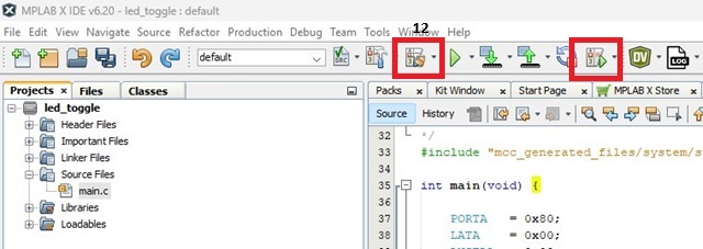
- Verify that LED0 is lit when SW0 is pushed on the Curiosity Nano board.