
1.2.3 Building and Running on PIC32MZW1 Curiosity (Wired or Wireless)
Downloading and Building the Application
To clone or download this application from Github, go to the main page of this repository and then click Clone button to clone this repo or download as zip file. This content can also be download using content manager by following these instructions.
Path of the application within the repository is apps/led_shadow_client_ecc/.
To build the application, refer to the following table and open the project using its IDE.
| Project Name | Description |
|---|---|
| firmware/pic32mz_w1_cur_wifi.X | MPLABX Project for PIC32MZW1 Curiosity board (Wireless solution) |
| firmware/pic32mz_w1_cur_eth.X | MPLABX Project for PIC32MZW1 Curiosity board (Wired solution) |
Provisioning the device for AWS account access
- Refer to Getting Started guide for setting up the AWS account based on your hardware configuration.
- With the completion of the above steps, the user would have got aws_clientcredential.h and aws_clientcredentialkeys.h, this may be used for running the demos.
Setting Up PIC32MZW1 Curiosity board
- Connect the MikroElectronika USB UART click Board to the mikroBUS connector on the Microchip PIC32 WFI32E Curiosity Board.
- Connect the MikroElectronika USB
UART click Board to your computer using a USB A to USB mini-B cable.
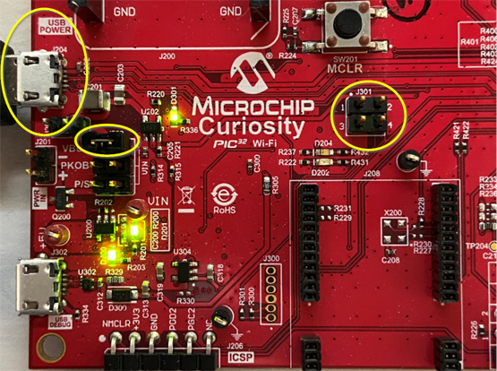
- Make sure that J202 jumper is connected to VBUS.
- Make sure J301 jumpers are open (Pins 1-2 open, Pins 3-4 open).
- For wired solution, connect PIC32 LAN8720 PHY Daughter Board AC3200043-3 to J208 connector on WFI32 Curiosity Board.
- To power supply the board , connect the USB Cable between USB Power J204 and your PC.
- Connect the MPLAB® ICD 4 tool or MPLAB PICKIT 4 between ICSP J206 connector and your PC, the detailed connection information can be found in the PIC32MZW1 Software User Guide, Chapter 2.1.3.
Building the Application
- Open the application project firmware/pic32mz_w1_cur_wifi.X (wireless) or firmware/pic32mz_w1_cur_eth.X (wired) in the IDE.
- Enter clientcredentialMQTT_BROKER_ENDPOINT and clientcredentialIOT_THING_NAME in aws_clientcredential.h.
- For Wi-Fi solution, enter the WIFI credentials in aws_clientcredential.h if not entered already.
- Build and program the application using the IDE.
Running the Application
- For wireless, ensure Wifi router
is connected to internet before turning on the board.
For wired, connect an Ethernet cable from an internet router to the PHY slot in PIC32MZW1 Curiosity board.
- If above step is successful then the Green LED (D204) on the board would turn ON/OFF once.
- Open the Terminal application (Ex.:Tera Term) on the computer.
- Configure the serial port settings as follows:
- Baud : 115200
- Data : 8 Bits
- Parity : None
- Stop : 1 Bit
- Flow Control : None
- Login to your AWS amazon account.
From the Services menu (upper left), click (or search for) IoT Core and open it. This will open the Aws IoT page as shown below.
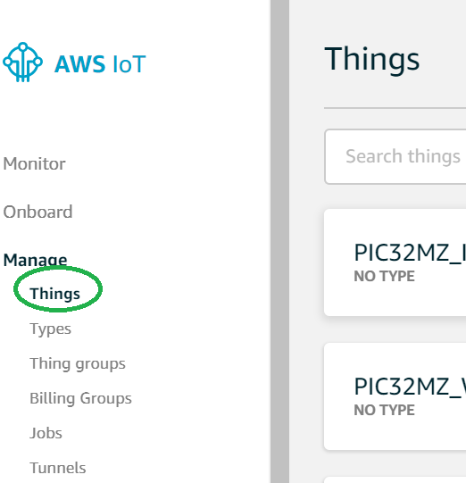
- From the menu on the left, Click "Manage" and then Click "Things". This will
display all the things managed by your AWS account in the right pane.
In the right pane, click the "Things" item, which represents your device.
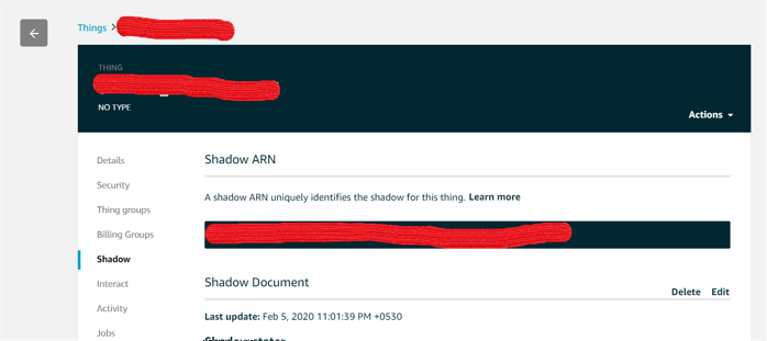
- The THING Name and Shadow ARN are masked for security reasons. Click on the "Shadow" item in the right pane. This will display the device shadow page.
- Build and Program the application using the MPLAB X IDE. The device will toggle
Green LED (D204) and now a shadow document will be created in the Device's
Shadow page.
The Shadow state document is JSON formatted file representing the device's state, in this example the LED status is depicted as device's status.
- The JSON variable "powerOn" indicates the LED state of the board and Shadow
state depicts the current state of the device.
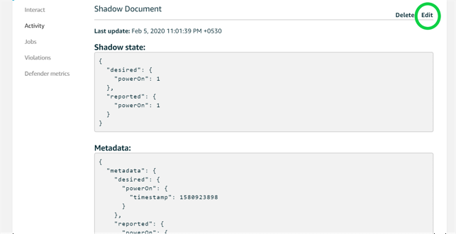
- The user can modify the Shadow state till the connection is alive by click on
the Edit button in the Shadow Document and changing the "powerOn" state.
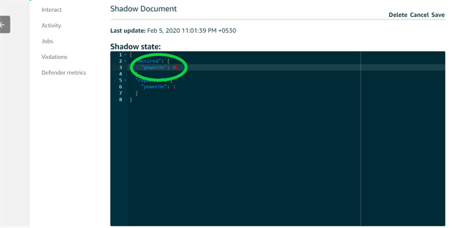
- Change the power On value to '1' and click on the Save Button, this will turn Green LED (D204) "ON". Changing the value to 0 will turn Green LED off.