
1.2.1.3.2 BLE Memory Usage for PIC32CX-BZ3
- Introduction
Optimizing memory usage is crucial for efficient BLE application development. This document provides a comprehensive guide on evaluating BLE memory usage, offing insights and best practices for developers.
- BLE Application
Composition
The architecture of an application encompasses its structural design and the integral components that constitute it. A standard BLE application is comprised of multiple essential elements, each fulfilling distinct roles. These elements, except for user implementation, can be broadly categorized into two segments: the application framework and the BLE. In addition, all the memory footprints listed below was calculated by configuring optimization level to 2.
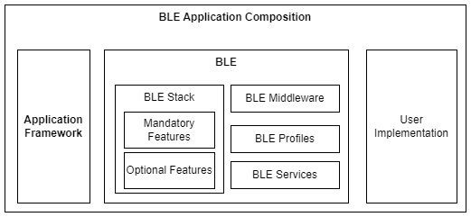
The overall memory footprint of the application is determined by the combined memory requirements of these components.
To accurately calculate the memory usage of a full-stack BLE application, one must consider the following elements:- Application Framework
- BLE
- BLE Stack - Full Stack Mode: This includes both mandatory elements and configurable options. The memory usage here varies depending on the supported GAP (Generic Access Profile) roles and any additional optional features that are implemented.
- BLE Middleware (Optional)
- BLE Profile (Optional)
- BLE Service (Optional)
For a BLE application operating in HCI (Host Controller Interface) mode, memory usage should be evaluated by considering the following components:- Application Framework
- BLE
- BLE Stack - HCI Mode: This is a specialized version of the BLE stack that is optimized for BLE controller only.
- Application
Framework
The application framework is an essential structure for application development, offering a suite of predefined functionalities and libraries that streamline the creation process. When developing a BLE application, certain components are necessary, especially for the PIC32CX-BZ3 H3 family of devices. These components include Device Support, Core, FreeRTOS, Persistent Data Storage (PDS), and Non-Volatile Memory (NVM). For the PIC32CX-BZ3 H3 family, additional specific components are required: EVSYS, Device Family Pack and System Component.
By utilizing these components, developers can efficiently build robust and feature-rich BLE applications tailored to the PIC32CX-BZ3 H3 family.
Table 1-16. Application framework memory footprint Static Data Memory(byte) Program Memory(byte) 1.6K 31K - BLE
The BLE stack is a critical component in wireless communication, but it can also be a substantial memory consumer. To optimize memory usage, it's crucial to assess the stack size requirements, which vary depending on the specific features enabled within the stack. Selecting the appropriate BLE stack mode and configuring it to include only the necessary features are key steps in managing memory consumption effectively in BLE-enabled devices.
- BLE
Stack
There are two primary modes of operation for the BLE stack: full stack and HCI mode. In full stack mode, the features are highly configurable, allowing developers to tailor the stack to meet the precise needs of their application, potentially reducing the memory footprint by disabling unnecessary features. On the other hand, HCI mode provides a comprehensive set of BLE controller capabilities without the need for manual configuration.
- Full
Stack Mode
The BLE stack is responsible for implementing the Bluetooth protocol stack necessary for BLE communication. It typically consists of several layers, including the Physical Layer (PHY), Link Layer, Logical Link Control and Adaptation Protocol (L2CAP), Attribute Protocol (ATT), Generic Attribute Profile (GATT), and Generic Access Profile (GAP). The BLE stack abstracts low-level Bluetooth operations, providing APIs for higher-level application layers to manage BLE connections, advertisements, data exchange, and security. The BLE stack is designed in a modularized fashion, with proper configuration, the BLE memory usage can be very efficient. The module unit is based on the GAP role; however, there is some common code shared between modules, so the overall memory consumption is not stacked.
- HCI
Mode
The BLE stack in HCI mode functions at the Host Controller Interface (HCI) layer. This mode ensures that the BLE stack communicates with the Bluetooth controller solely via HCI commands and events, effectively encapsulating the complexities of the lower-level Bluetooth protocol stack. By operating in HCI mode, the BLE stack provides comprehensive support for the entire range of BLE controller features. However, it is important to note that in this mode, program memory usage is fixed and cannot be modified or optimized by the user.
Table 1-17. BLE stack memory footprint BLE Stack (byte) Static Data Memory Dynamic Data Memory Program Memory Full Stack Mode Adv / Peripheral 1.9K 13K (Only one BLE connection condition is included) + TX_BUFFER_SIZE 122K Scan / Central 2.5K 13K (Only one BLE connection condition is included) + TX_BUFFER_SIZE 134K Adv / Peripheral / Scan / Central 2.5K 15K (Only one BLE connection condition is included) + TX_BUFFER_SIZE 140K HCI Mode 2.6K 15K (Only one BLE connection condition is included) + TX_BUFFER_SIZE 150K ** Optimizing the TX_BUFFER_SIZE: Balancing Packet Queue Length and Size The TX_BUFFER_SIZE is a pivotal parameter in BLE applications, directly impacting the efficiency and performance of data transmission. It is calculated by considering two primary factors: the maximum number of queued Transmission (TX) packets and the length of each TX packet, inclusive of any additional overhead. To determine the appropriate TX_BUFFER_SIZE, one must multiply the maximum number of queued TX packets by the sum of the maximum length of a TX packet and the overhead bytes. For instance, if the maximum length of a TX packet is 247 bytes, the overhead is typically accounted for by rounding up to a convenient number, 256 bytes. In a BLE application, reserving space for four queued TX packets of maximum length is often adequate for routine operations. This setup ensures a balance between memory allocation and the ability to handle a reasonable amount of data transmission tasks without significant delays. However, applications demanding higher throughput will necessitate a larger TX_BUFFER_SIZE. This is to accommodate the increased volume of data being transmitted without sacrificing transmission speed or reliability. In such cases, the maximum TX_BUFFER_SIZE would be calculated as 12 (the number of queued TX packets) multiplied by 256 bytes (the adjusted packet size including overhead), resulting in a buffer size of 3072 bytes. It is essential to fine-tune the TX_BUFFER_SIZE according to the specific needs of the BLE application. A larger buffer size may enhance throughput but at the cost of increased memory usage, while a smaller buffer size may conserve memory but potentially reduce throughput.
For example, the TX_BUFFER_SIZE would be set to 1K if the maximum queued is 4 with maximum TX packet length.
** A single BLE connection necessitates 1.1 KB of data memory. If the BLE application requires a multi-link scenario, additional data memory must be allocated for the BLE stack.
To cater to the diverse needs of various applications, the BLE stack offers a suite of optional features that can be fine-tuned by users. Below is an overview of these configurable optional features:- Extended Advertising
- Extended Scan
- Periodic Advertising
- Periodic Sync
- Extended Central
- GATT Client (Not applicable to HCI mode; it is only valid in the full stack mode)
- L2CAP COC (Not applicable to HCI mode; it is only valid in the full stack mode)
Optional features memory footprint
- Extended Advertising
- Program Memory: 15K bytes (Not applicable to HCI mode, as the cost is already included in the HCI mode program memory)
- Static Data Memory: 0.4K bytes
- Dynamic Data Memory: The basic memory requirement is 2K bytes; however, additional memory may be necessary to accommodate advertising data of varying lengths.
Advertising Data Length(byte) Additional Memory(byte) 1-23 0 24-151 0.125K 152-243 0.25K 244-285 0.375K 286-412 0.5K 413-487 0.625K 488-547 0.75K 548-731 1K - Extended Scan
- Program Memory: 8K bytes (Not applicable to HCI mode, as the cost is already included in the HCI mode program memory)
- Static Data Memory: 0.1K bytes
- Dynamic Data Memory: The basic memory requirement is 2K bytes; however, additional memory may be necessary to handle variable-length advertising data.
Advertising Data Length(byte) Additional Memory(byte) 1-244 0 245-230 0.25K 321-572 0.75K 573-732 1K 733-976 1.5K - Periodic Advertising
- Program Memory: 18K bytes (Not applicable to HCI mode, as the cost is already included in the HCI mode program memory)
- Static Data Memory: 0.4K bytes
- Dynamic Data Memory: The basic memory requirement is 2K bytes; however, additional memory may be necessary to accommodate advertising data of varying lengths.
Advertising Data Length(byte) Additional Memory(byte) 1-200 0 201-269 0.25K 270-397 0.5K 398-499 0.75K 500-592 1K - Periodic Sync
- Program Memory: 15K bytes (Not applicable to HCI mode, as the cost is already included in the HCI mode program memory)
- Static Data Memory: 0.2K bytes
- Dynamic Data Memory: The basic memory requirement is 1K bytes; however, additional memory may be necessary to handle variable-length advertising data.
Advertising Data Length(byte) Additional Memory(byte) ~488 0 489-876 0.25K 877~1066 0.75K 1067~1256 1K - Extended Central
- Program Memory: 3K bytes (Not applicable to HCI mode, as the cost is already included in the HCI mode program memory)
- GATT Client
- Program Memory: 4K bytes
- L2CAP COC
- Program Memory: 5K bytes
- Static Data Memory: 0.4K bytes
- Dynamic Data Memory: 0.8K bytes
- Full
Stack Mode
- BLE
Middleware
BLE Middleware sits between the application layer and the BLE stack. It provides additional functionality and abstraction to simplify the development of BLE applications. Middleware may include modules for managing device discovery, connection establishment, and security protocols. The BLE Middleware abstracts complex BLE operations, enabling developers to focus on application logic rather than low-level Bluetooth protocol details. Each submodule in BLE middleware is configurable and removable. The table below shows the valid condition for the submodule usage.
GAP Role Adv / Peripheral Scan / Central Adv / Peripheral / Scan / Central Submodule Device manager V V V Database Discovery V
(If GATT Client supported)
V
(If GATT Client supported)
V
(If GATT Client supported)
Service Change Manager V V V Log V V V Table 1-18. BLE middleware memory footprint BLE Middleware(byte) Static Data Memory Program Memory Device manager 0.2K 5K Database Discovery < 10 2K Service Change Manager < 50 2K Log < 10 7K - BLE
Profile
A BLE Profile defines a set of protocols tailored to a specific use case or application. Profiles streamline the development of BLE applications by providing a common framework for defining device functionality and communication protocols. Each BLE profile is a standalone unit, and users can determine whether the BLE profile is required or not.
Table 1-19. BLE profile memory footprint BLE Profile(byte) Static Data Memory Program Memory ANCS (Alert Notification Center Service) 2.2K 2.8K ANPC (Alert Notification Profile - Client) 0.5K 1.8K ANPS (Alert Notification Profile - Server) 0.1K 1K HOGPS (HID over GATT Profile - HID Device) 0.1K 1.5K OTAPC (Over the Air Profile - Client) 0.5K 2.5K OTAPS (Over the Air Profile - Server) 0.2K 3K PXPM (Proximity Profile - Monitor) 0.5K 2K PXPR (Proximity Profile - Reporter) 0.1K 0.6K TRCBPS (Transparent Credit Based Profile - Server) 0.8K 2.5K TRSPC (Transparent Profile - Client) 1.5K 3K TRSPS (Transparent Profile - Server) 1.2K 2K - BLE
Service
A BLE Service is a collection of related characteristics that define a specific functionality or feature of a BLE device. Services are organized hierarchically within the GATT (Generic Attribute Profile) structure and are identified by unique UUIDs (Universally Unique Identifiers). Each service is a standalone unit, and developer can determine whether the BLE service is required or not.
Table 1-20. BLE service memory footprint BLE Service(byte) Static Data Memory Program Memory ANS (Alert Notification Service) 0.2K 0.1K BAS (Battery Service) 0.1K 0.1K DIS (Device Information Service) 0.5K 1K HIDS (Human Interface Device Service) 0.6K 1.5K IAS (Immediate Alert Service) 0.1K 0.1K LLS (Link Loss Service) 0.1K 0.1K OTAS (Over the Air Service) 0.2K 0.2K TPS (TX Power Service) 0.1K 0.1K TRCBS (Transparent Credit Based Service) 0.2K 0.1K TRS (Transparent Service) 0.2K 0.1K
- BLE
Stack