1 MCC Melody Bootloader: 8-bit
Introduction
The MPLAB® Code Configurator (MCC) Melody 8-bit Bootloader Module is the new implementation of the 8-bit Bootloader Library from MPLAB® X Code Configurator(MCC) Classic ported into the newly designed MCC Melody framework. It includes some new features as well as continued support for past communication protocols and memory interfaces present in the Classic version of MCC. It is important to note that not all of the devices that were supported by MCC Classic are still supported today in MCC Melody. Refer to the list of supported devices that resides in the release notes if unsure about the support status of any device. Refer to the library release notes for the version information, dependencies, and for the required specific versions of the MCC libraries and drivers.
Basic Bootloader Overview
A bootloader is used when the user or manufacturer wants a way to update the firmware of their device in the field with a new application while minimizing device downtime. To do this, the device in the field needs some type of communication method that is capable of passing data between the device that needs an update (the “target device”) and a PC or other device which holds the new application firmware that needs to be installed (the “host app”). This implies that the device in the field must contain not only the end application, but another piece of software that controls the loading and unloading of that end application. While its possible for each application to write their own handler to achieve this, writing firmware to update another firmware on a device is a non-trivial process that usually requires a deep understanding of the device operation, the software compiler and linker options, as well as the software running on the updating device like a PC. Because of this steep and broad learning curve, Microchip provides the basic bootloader infrastructure for their devices in an easy to configure library.
Basic Bootloader Infrastructure
A bootloader infrastructure has 3 main parts shown below. The bootloader firmware, the end application, and the external device used to transfer the new application image to the target device, also known as a Host (either another device, a host PC or the Unified Bootloader Host Application by Microchip).
The bootloader firmware is a piece of software that first runs when the device comes out of a Reset state. Its first task is to verify whether or not the application on the device is valid. If the application is verified, control of the Microcontroller Unit(MCU) is transferred over to the end application. If verification fails, step into the bootloader operation cycle and wait for an attempted bootloader task to be started by the host application. The bootloader can also check for specific signals on the device to start the update process of the firmware. This could be as simple as checking the value of a GPIO pin or checking for a specific type of traffic on the UART indicating that there is a new application firmware version that needs to be installed.
The end application is the second part of the infrastructure. This is a suite of code fully written and controlled either by the user or the manufacturer and it is this application that will be installed by the bootloader. Future sections of this document will be showing some example bootloader projects where a blinking LED application is used to demonstrate how to start loading a custom application with a bootloader solution.
Finally, the last part of any bootloader infrastructure is the method used to transfer the new application firmware from an external host PC or device to the target device located in the field. The host application used to manage the bootload process can be either The Unified Bootloader Host Application, a custom made stand-alone application written by the user or another 3rd-party source, or a separate external Microcontroller device. Either way, the end purpose remains the same; updating the end application firmware version through use of the Bootloader API and supported commands.

Verification Features
A bootloader is the low-level code that runs when the device comes out of a Reset state. Its main purpose is to check to see if there is a new application image that needs to be installed on the device, and if there is, provide a path to accomplish this task. More features can be added into bootloaders that improve their performance and safety. One example of an important feature of any bootloader is going to be the bootloader’s verification options. Bootloaders provide these verification schemes to check the validity of the application code before transferring control to the end application. Microcontrollers are basically just small computers and therefore should be protected just like any other computer system. In order to do this with a bootloading process, the bootloader needs to be able to identify errors in the application code before running it, which inherently protects the MCU from running malicious or corrupted code. Read more on this topic in the Verification Schemes chapter.
Memory Provisioning Features
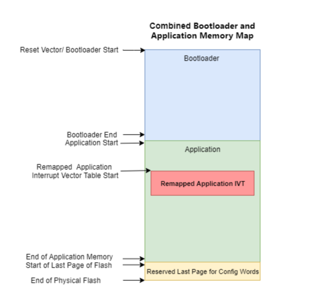
Another feature of the MCC Melody 8-bit Bootloader is its communication interface designed specifically to warrant communication of commands used to transfer bytes of the application image into program memory of the microcontroller. As previously mentioned, to utilize a bootload process the bootloader code must be programmed into the microcontroller unit’s Flash memory. It is necessary to provision the MCU’s Flash memory to prevent writing in the boot section as well as to tell the MCU where to write the new application image and how much data the application is allowed to access. Figure 2 shows the provisioned memory layout of a general bootloader solution.