
1.1 AC PWM Generation
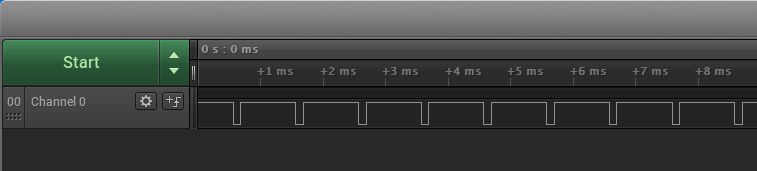
This example application shows how to use the Analog Comparator Peripheral library to generate a 1 kHz PWM waveform.
Description
The AC peripheral is configured to generate analog PWM waveform by comparing the sine wave generated from the DAC with the reference voltage selected as a VDD scaler. The duty cycle of the analog PWM is changed by pressing a switch which changes the value of the VDD scaler.
Downloading and Building the Application
To clone or download this application from Github, go to the main page of this repository and then click Clone button to clone this repository or download as zip file. This content can also be downloaded using content manager by following these instructions.
Path of the application within the repository is apps/ac/ac_wav_gen/firmware.
To build the application, refer to the following table and open the project using its IDE.
| Project Name | Description |
|---|---|
| pic32cm_mc00_curiosity_pro.X | MPLABX project for PIC32CM MC00 Curiosity Pro Evaluation Kit |
Setting Up the Hardware
The following table shows the target hardware for the application projects.
| Project Name | Board |
|---|---|
| pic32cm_mc00_curiosity_pro.X | PIC32CM MC00 Curiosity Pro Evaluation Kit |
Setting Up PIC32CM MC00 Curiosity Pro Evaluation Kit
- Use a jumper wire to connect pin PA04 “Pin A2 of the J803 connector” and PA02 “Pin DAC_VOUT on the DAC Header J700”
- Use the Logic Analyzer/Oscilloscope and probe PA12 pin (Pin 11 of the EXT1 header) to observe the PWM output
- Connect the Debug USB port on the board to the computer using a micro USB cable
Running the Application
- Build and Program the application using its IDE
- Observe the PWM waveform using the oscilloscope connected to the PWM output
pin
- Press switch to change the duty cycle of PWM waveform
Refer to the following table for PWM output and switch details:
| Board | PWM Output Pin | Switch Name |
|---|---|---|
| PIC32CM MC00 Curiosity Pro Evaluation Kit | PA12 pin (Pin 11 of the EXT1 header) | SW0 |