3.3.2 16-bit Counter (Mode1)
When the RTC Operating Mode bits in the Control A register (CTRLA.MODE) are
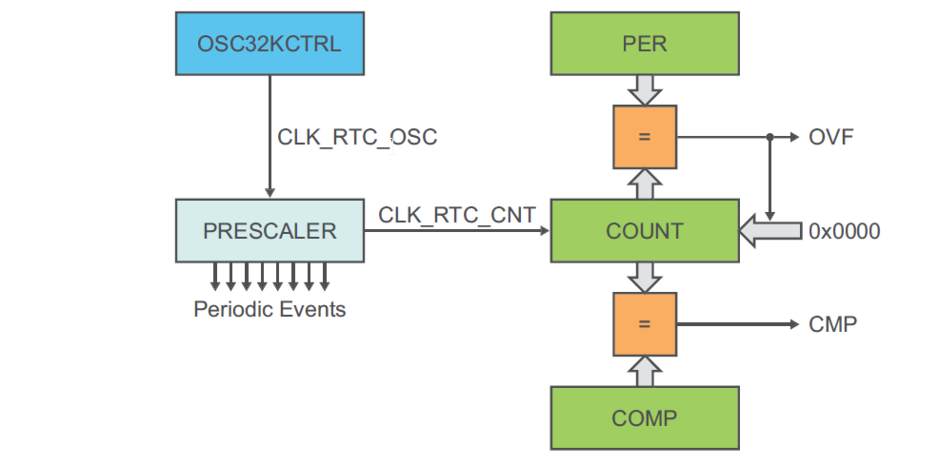
1, the counter operates in 16-bit Counter mode as shown in the following figure, RTC
Block Diagram (Mode 1 — 16-Bit Counter). When the RTC is enabled, the counter will
increment on every 0-to-1 transition of CLK_RTC_CNT. In 16-bit Counter
mode, the 16-bit Period register (PER) holds the maximum value of the counter. The
counter will increment until it reaches the PER value, and then wrap to 0x0000. This
sets the Overflow Interrupt flag in the Interrupt Flag Status and Clear register
(INTFLAG.OVF).
The RTC counter value can be read from or written to the Counter Value register (COUNT) in 16-bit format.
The counter value is continuously compared with the 16-bit Compare registers (COMPn, n=0..1). When a compare match occurs, the Compare n Interrupt flag in the Interrupt Flag Status and Clear register (INTFLAG.CMPn, n=0..1) is set on the next 0-to-1 transition of CLK_RTC_CNT.