6.3 mikroBUS™ Socket and Kit Power Supply
When the ATmega4809 Xplained Pro board is powered from an off state, the on-board EDBG tries to read ID chips from all the Xplained Pro extension connectors to determine the maximum allowed voltage that can be applied. The EDBG uses this information to decide if it can safely open the power switch shown in the block diagram below.
The mikroBUS connector is powered directly from the 3.3V and 5.0V power rails shown in the block diagram. If a mikroBUS add-on board is connected when the board is powered up, the voltage can leak through the mikroBUS connector to the ATmega4809 through its I/O pins while the power switch is closed.
In a worst-case scenario powering the ATmega4809 through its I/O pins can damage the device and/or cause a power-on-latch-up where the firmware in the ATmega4809 does not start and the only possible recovery method is a power cycle. The failures and severity of this problem are determined by how the mikroBUS add-on board is designed and how the power nets are related to the I/O pins on the board.
Work Around
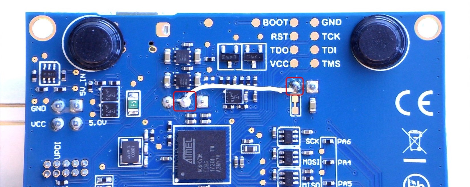
Bypassing the power switch shown in the block diagram above will prevent the power-up problems. The work around is to short-circuit J105 pin 2 and J103 pin 2, as shown in the image below.

Revision 5 of ATmega4809 Xplained Pro already implements this hotfix.
Affected Kit Revisions
This design flaw affects revision 3, 4, and 5 of ATmega4809 Xplained Pro.
