The STK600
board connected to Atmel Studio 7.0 via the on-board USB connector.
Workflow
Launch Atmel Studio 7.0.
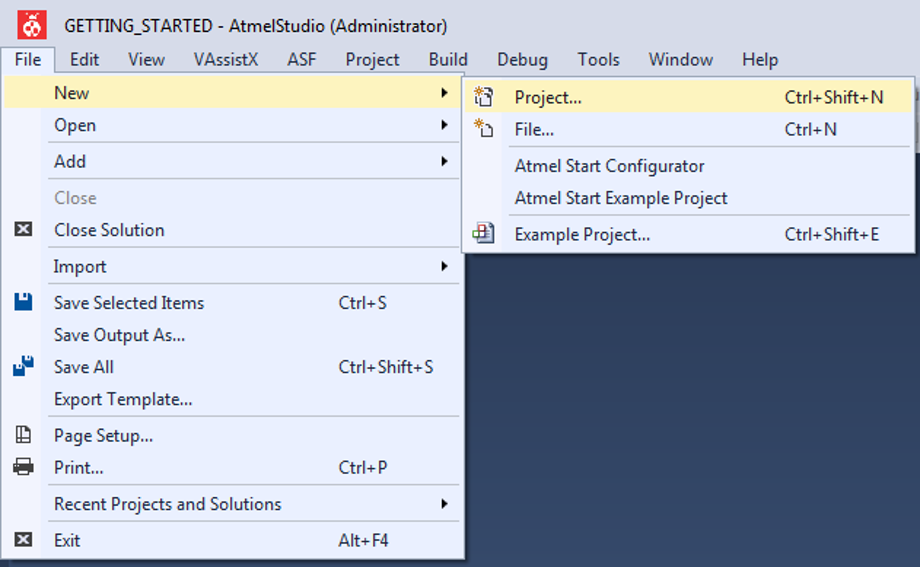
Start creating a new project by clicking
New → Project... or by using the shortcut Ctrl+Shift+N, as shown in the
figure below.Figure 5-7. Create New Project in Atmel
Studio
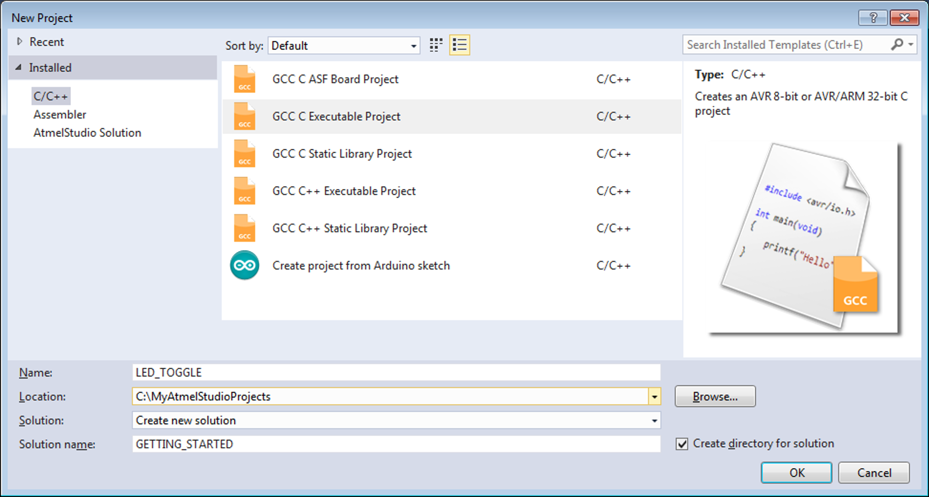
Select the GCC C Executable Project
template from the new project wizard shown in the figure below, type in the name of the
solution and project (e.g. GETTING_STARTED and LED_TOGGLE), and click
OK.Figure 5-8. New Project Wizard
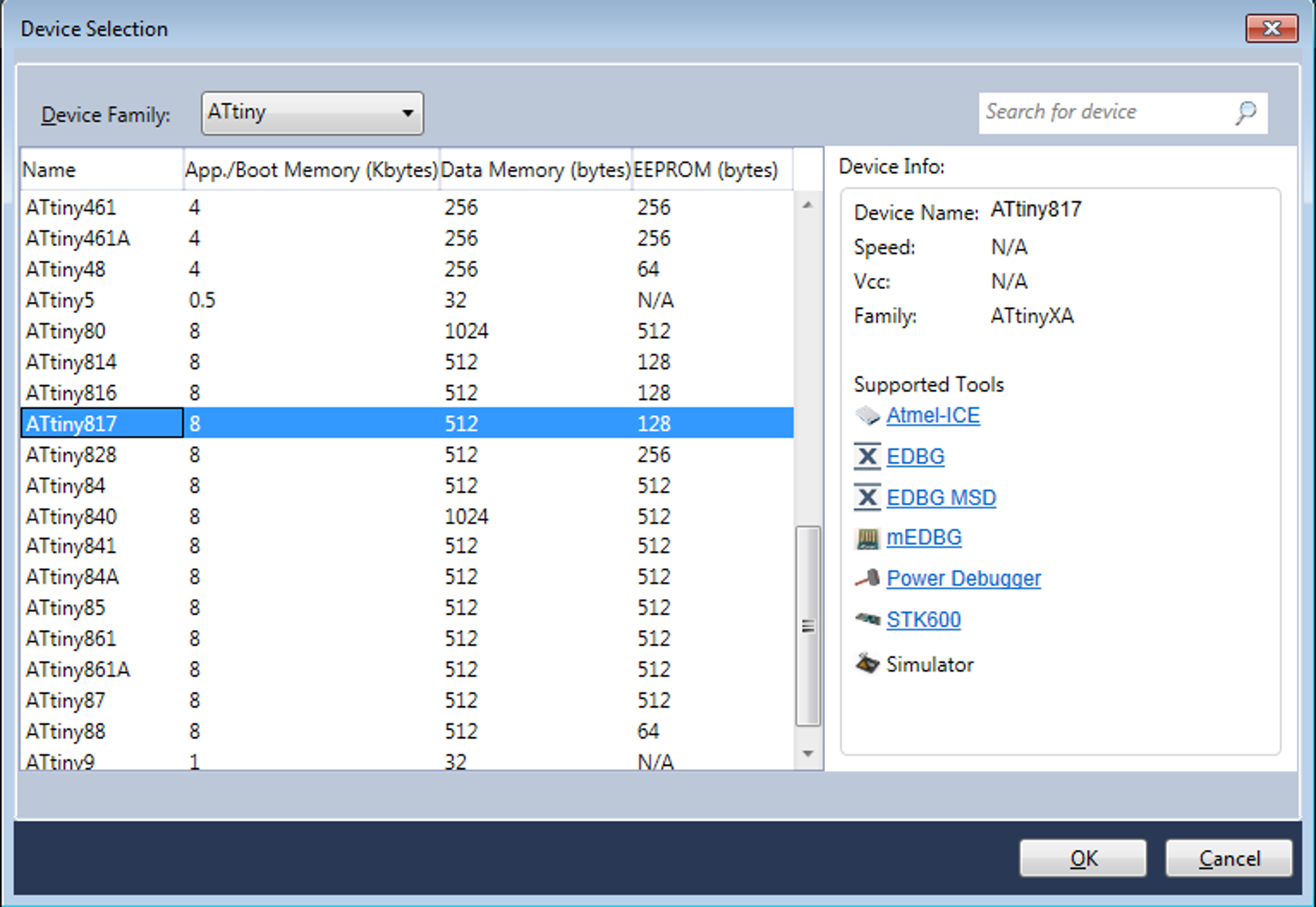
Select ATtiny817 from the device selection wizard as shown in the
figure below, and click OK.Figure 5-9. Device Selection WizardA new project with a main.c file associated with it will be generated in Atmel
Studio.
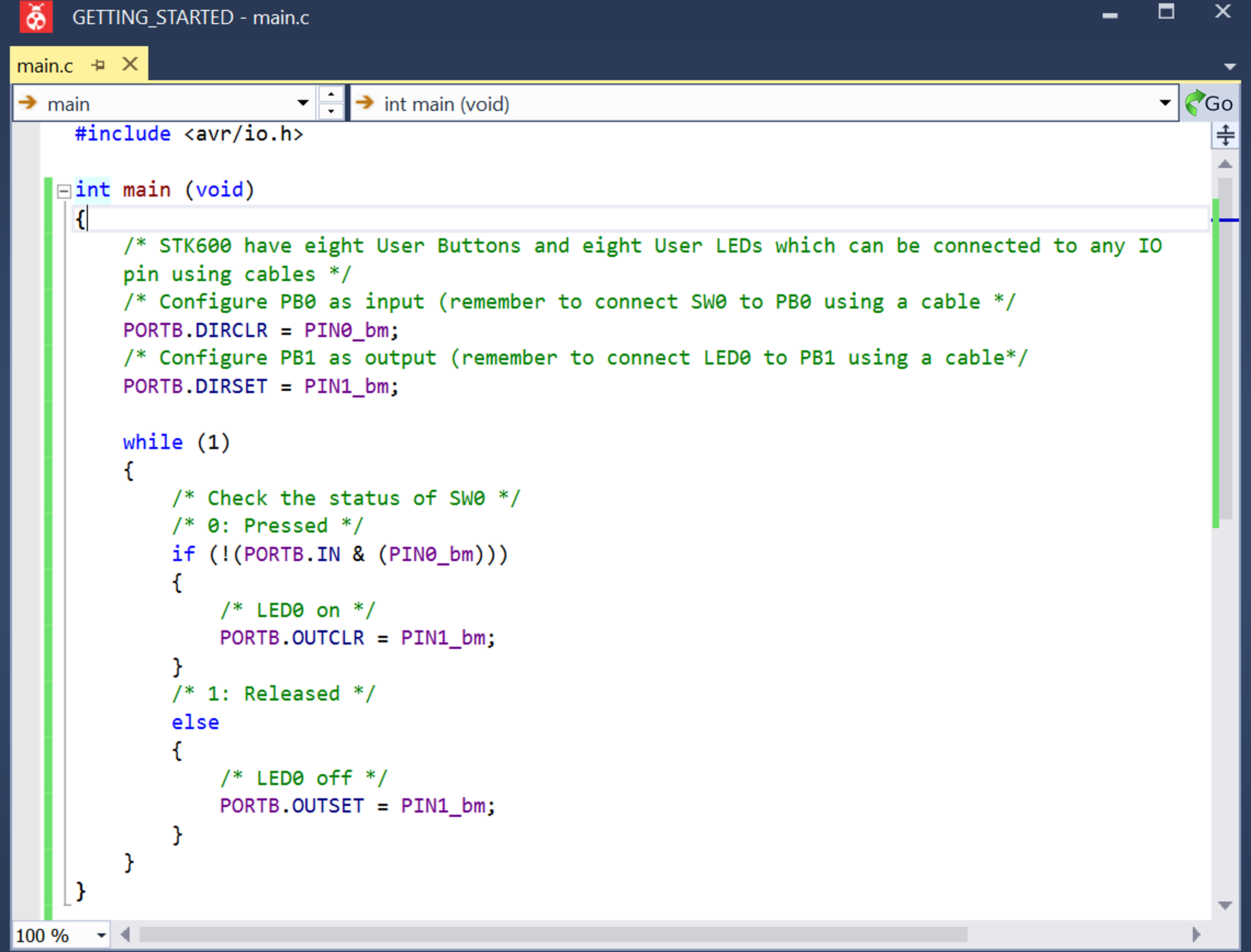
Replace the main function in the
main.c file with the following code
snippet:
int main (void)
{
  /* STK600 have eight User Buttons and eight User LEDs which can be connected to any IO pin using cables */
  /* Configure PB0 as input (remember to connect SW0 to PB0 using a cable */
  PORTB.DIRCLR = PIN0_bm;

  /* Configure PB1 as output (remember to connect LED0 to PB1 using a cable*/
  PORTB.DIRSET = PIN1_bm;

  while (1)
  {
    /* Check the status of SW0 */
    /* 0: Pressed */
    if (!(PORTB.IN & (PIN0_bm)))
    {
      /* LED0 on */
      PORTB.OUTCLR = PIN1_bm;
    }
    /* 1: Released */
    else
    {
      /* LED0 off */
      PORTB.OUTSET = PIN1_bm;
    }
  }
}
In
the code editor, the code should appear as shown in the figure below.Figure 5-10. Code Editor Window
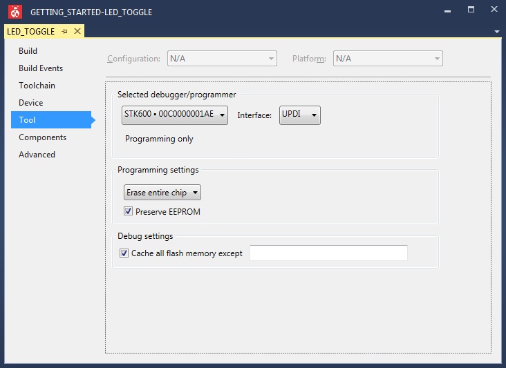
Open project properties by clicking
Project → Properties or by using the shortcut ALT+F7.
In the Tool view (see the figure
below) set Selected debugger/programmer to STK600 and Interface to UPDI.Figure 5-11. Debugger and Interface for ATtiny817
Build the project by clicking Build →
Build Solution or using the shortcut F7.
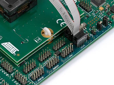
Connect the embedded debugger on STK600 to ATtiny817 by connecting a cable between the ISP/PDI headers,
as shown in the figure below.Figure 5-12. UPDI Connection on STK600
Connect PC5 to SW0, and PC0
to LED0 by using cables.
Load the code onto the STK600 and start debugging by clicking
Debug → Start debugging and break or by using the shortcut ALT+F5. The
application is programmed onto the device and the program execution should break in
main.
Run the code by clicking Debug →
Continue or by using the shortcut F5.
Verify that LED0 is lit when SW0 is pushed
on STK600.
The online versions of the documents are provided as a courtesy. Verify all content and data in the device’s PDF documentation found on the device product page.