
3.1.1 Ethernet and PoE Port State
The following figure shows the front panel of the unit.
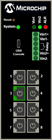
Ethernet Link status is represented by the RJ45 surrounding color. PoE status is represented by the image inside the RJ45 connector. The top Vin1, and Vin2 report on which pair (can be both) a power is applied by turning the respective LED to green. The alarm red LED will be turned on when power is provided only to Vin1 or Vin2, and not both.
The following table lists the Ethernet link LED images and their descriptions.
| Ethernet Link LED Images | Description |
|---|---|

 | The Ethernet link is ON; 1000MB (RJ45 is green) and 10/100MB (RJ45 is orange) |
 | The Ethernet link is OFF (RJ45 in gray) |
 | The Ethernet link is disabled (RJ45 with gray cross) |
 | PoE is enabled |
 | PoE is disabled (no power indicator circle inside RJ45) |
 | PoE power applied to PoE-PD device |
 | Fail to communicate with the PoE controller – Text inside RJ45 |
 | Fail to power PD. Insufficient free power (W) – text inside RJ45 |
 | PoE fault—Fail to power PD – text inside RJ45 |
 | PoE overload—PD power consumption exceeded the maximum limit – text inside RJ45 |