
3.2 GUI Connection, Device Detection, and Host/Client Verification
The GUI displays detected devices in the device list and allows each module to be selected and configured individually. For complete register and PMBus command descriptions, refer to the MCPF1525M06 data sheet.
Use the following procedure to power the dual-module reference design, connect the GUI interface, and verify that both MCPF1525M06 devices are detected for individual monitoring and configuration. The Host/Client roles are defined by the hardware PS configuration.
- Connect a nominal 12V input supply to the reference design board and power the board.
- Ensure that the bias VCC is active. In this reference design, VCC is selected using J1, either from U1_VCC or from an external VCC source.
- Connect the MCP2221A Breakout Module to the board telemetry header J4 to enable I2C/PMBus communication with the two MCPF1525M06 modules.
- Open the MCPF1525M06 GUI. If the devices are not detected automatically, click Scan. The GUI shows the detected devices in the device list.
The U1 Host device is normally detected automatically, and its I2C/PMBus addresses are loaded in the GUI device view, as shown in Figure 3-1.
Confirm the following Host addresses:
- U1 I2C Address: 0x10
- U1 PMBus™ Address: 0x70
Figure 3-1. GUI Device Detection and U1 Host Successful Configuration for I2C/PMBus Communication and Monitoring Interface 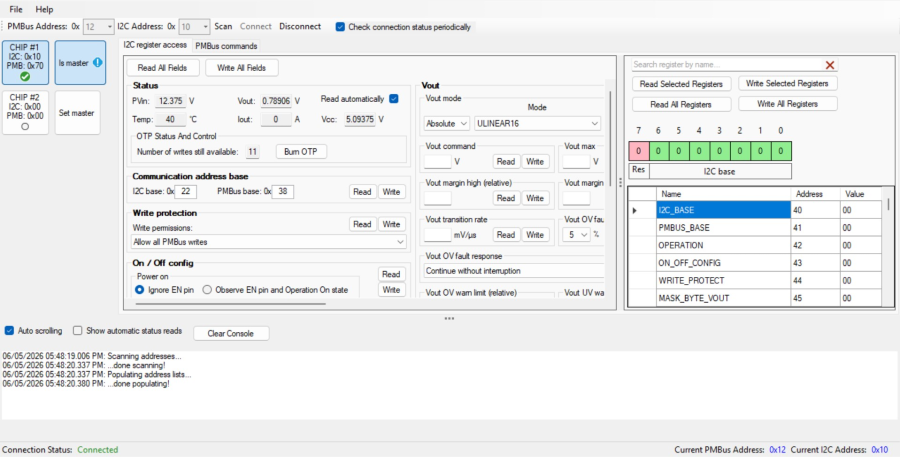
Figure 3-2. GUI View When Selecting U2 Device (On Top Left of GUI Device Screen) 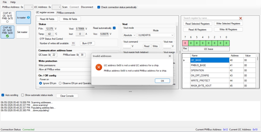
As observed in Figure 3-2, in the present GUI version, the Client address may not be loaded automatically in the Client device view. The GUI may detect that two devices are present, but the Client register values may not be readable until the Client address is manually assigned.
To enable Client access:
- Right-click the Client device entry in the GUI device list
- Set the Client I2C address to 0x12
- Set the Client PMBus address to 0x72
After this address update, the GUI can read the Client registers and allows monitoring and configuration of the Client module as illustrated in Figure 3-3.
Figure 3-3. GUI Device Detection and U1 Host Successful Configuration for Telemetry 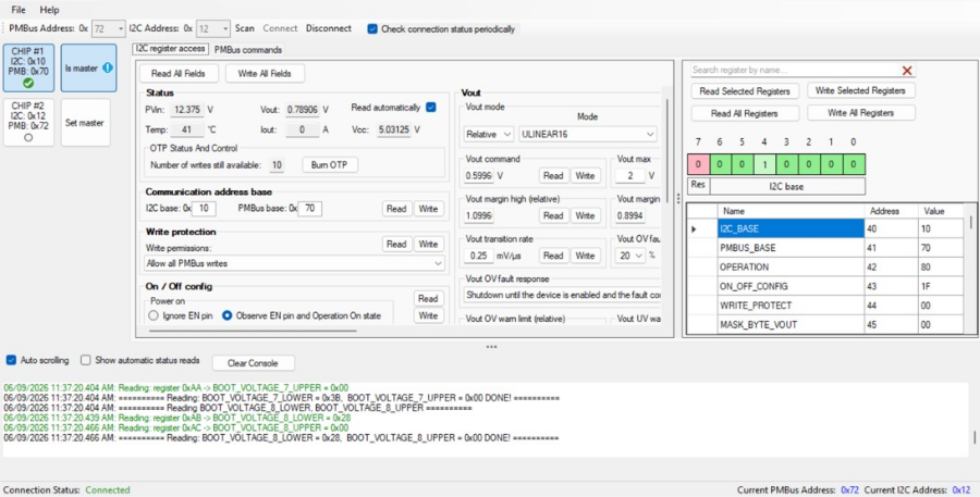
- Select each detected module individually in the GUI before reading or writing configuration registers.