3 Hardware Features
The following is a list of features of Mixed Signal DC:
- Test points for signal probing
- Mixed signal header for daughter card support
- 100 mil header for wire-wrapped or soldered signals
The following table lists the test point signals of Mixed Signal DC.
| TP | Signal | TP | Signal | TP | Signal | TP | Signal |
|---|---|---|---|---|---|---|---|
| TP1 | MSS_GP_IO_0 | TP16 | MSS_GP_IO_15 | TP31 | AC2 | TP46 | ADC3 |
| TP2 | MSS_GP_IO_1 | TP17 | F2-200-IO_0 | TP32 | ATGND1 | TP47 | ADC6 |
| TP3 | MSS_GP_IO_2 | TP18 | F2-200-IO_2 | TP33 | AC3 | TP48 | ADC5 |
| TP4 | MSS_GP_IO_3 | TP19 | F2-200-IO_1 | TP34 | AT3 | TP49 | ADC8 |
| TP5 | MSS_GP_IO_4 | TP20 | F2-200-IO_3 | TP35 | AC4 | TP50 | ADC7 |
| TP6 | MSS_GP_IO_5 | TP21 | F2-200-IO_4 | TP36 | AT4 | TP51 | ADC10 |
| TP7 | MSS_GP_IO_6 | TP22 | F2-200-IO_5 | TP37 | AV1_1 | TP52 | ADC9 |
| TP8 | MSS_GP_IO_7 | TP23 | F2-200-IO_6 | TP38 | ATGND2 | TP53 | AC1 |
| TP9 | MSS_GP_IO_8 | TP24 | F2-200-IO_8 | TP39 | AV1_3 | TP54 | ADC11 |
| TP10 | MSS_GP_IO_9 | TP25 | F2-200-IO_7 | TP40 | AV2_1 | TP55 | VEX_5V |
| TP11 | MSS_GP_IO_10 | TP26 | PWM1 | TP41 | AV2_4 | TP56 | V3P3 |
| TP12 | MSS_GP_IO_11 | TP27 | PWM0 | TP42 | AV2_3 | TP57 | GND |
| TP13 | MSS_GP_IO_12 | TP28 | DACOUT1 | TP43 | ADC2 | TP58 | GND |
| TP14 | MSS_GP_IO_13 | TP29 | DACOUT0 | TP44 | AV1_4 | — | — |
| TP15 | MSS_GP_IO_14 | TP30 | AT2 | TP45 | ADC4 | — | — |
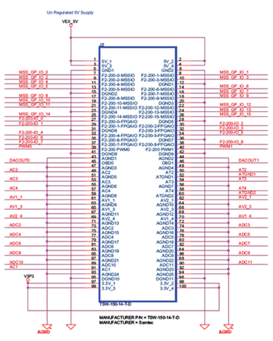
The following figure shows the mixed signal connector that connects directly to the SmartFusion Evaluation Kit or Development Kit mixed signal header.

The following figure shows that the second connector can be used to probe signals or build add on connectors. It does not connect to any other Microchip-specific hardware.