
2.2 MPLAB PICkit Basic In-Circuit Debugger Components
The components of the MPLAB PICkit Basic In-Circuit Debugger system are show in the figure and described below.
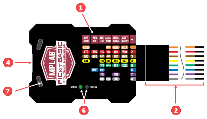
- MPLAB PICkit Basic enclosure with a color-coded signals label on the front. This
includes a pin 1 specifier
 .
. - 8-pin SIL connector with color-coded wires on the bottom of the enclosure. These correspond to the color-coded signals label on the front.
- Alternately, you could use the 8-pin to 10-pin ARM SWD Adapter Board.
- USB Type-C® connector on the top of the enclosure.
- Use the included full-featured USB Type-C® cable (data and power) to connect to a computer.
- Two status LEDs on the front of the enclosure.
- Emergency Recovery button accessible through the left side of the enclosure.
To use the MPLAB PICkit Basic, you will need to supply:
- Target board.
- Power supply for target board.
- Any wiring interfaces or cables needed for your application. Some available adapters and cables include the AC164110 RJ-11 to ICSP Adapter.
Additional hardware and accessories may be ordered separately from Microchip Direct .
- Debugger Adapter Board (Part Number AC002015) - a connectivity board that supports JTAG, SWD and ICSP protocols, useful for debugging AVR® with MPLAB PICkit Basic.