1.1 ADC Polling
This example demonstrates how to sample an analog input in polled mode and send the converted data to console.
Description
In this example, Analog input voltage in the range of 0V to 3.3V is fed to the ADC and converted value is displayed on the console. The ADC conversion is triggered by software and result is polled using status API.
Downloading and Building the Application
To clone or download this application from Github, go to the main page of this repository and then click Clone button to clone this repository or download as zip file. This content can also be downloaded using content manager by following these instructions.
Path of the application within the repository is apps/adc/adc_polled_mode/firmware.
To build the application, refer to the following table and open the project using its IDE.
| Project Name | Description |
|---|---|
| sam_g55_xpro.X | MPLABX project for SAM G55 Xplained Pro Evaluation Kit |
Setting Up the Hardware
The following table shows the target hardware for the application projects.
| Project Name | Description |
|---|---|
| sam_g55_xpro.X | SAM G55 Xplained Pro Evaluation Kit |
Setting Up SAM G55 Xplained Pro Evaluation Kit
- AD0 pin is used for analog input
- Use a jumper wire to connect Pin 3 of EXT1 (AD0 is mapped to Port Pin PA17) to 3.3V or GND
- Connect the Debug USB port on the board to the computer using a micro USB cable
Running the Application
- Open the Terminal application (Ex.:Tera term) on the computer
- Connect to the EDBG Virtual COM port and configure the serial settings as
follows:
- Baud : 115200
- Data : 8 Bits
- Parity : None
- Stop : 1 Bit
- Flow Control : None
- Build and Program the application project using its IDE
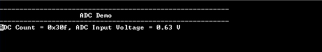
- Console displays the ADC Count and the ADC Input Voltage