4.2 JTAG Interface
Few devices have a JTAG interface that can be used for both programming and debugging. The JTAG lines are shared with analog input and must be connected so that the JTAG programmer can control the lines. JTAG programming tools can drive a resistive load, however, it is better to avoid capacitive load.
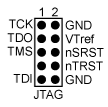
The following figure shows the standard JTAG connector supplied with ISP programmers. For the SPI programming connector, the target’s voltage supply allows power to the device or ensures correct signal levels when programming.

Note: Refer to the specific user guide of
programmers/debuggers for more information about the JTAG interfacing with AVR
devices.
