3.2.2 Target Connection Circuitry
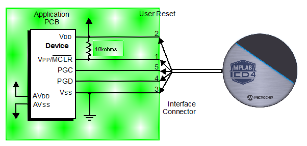
The figure below shows the interconnections of the MPLAB ICD 4 In-Circuit Debugger to the connector on the target board. The diagram also shows the wiring from the connector to a device on the target PCB. A pull-up resistor (usually around 10 kΩ) connected from the VPP/MCLR line to the VDD is recommended so that the line may be strobed low to reset the device.

