4 MCC Melody Components
The Libraries, Drivers and Hardware peripherals, which make up MCC Melody, are collectively referred to as components. Also what is Configuration- vs. Firmware portability.
The Libraries, Drivers and Hardware peripherals, which make up MCC Melody, are collectively referred to as components. Libraries and Drivers are not directly dependent on any microcontroller (MCU) hardware, relying on PLIBs (Peripheral Libraries), which provide the hardware abstraction. The following figure shows MCC Melody's structure.
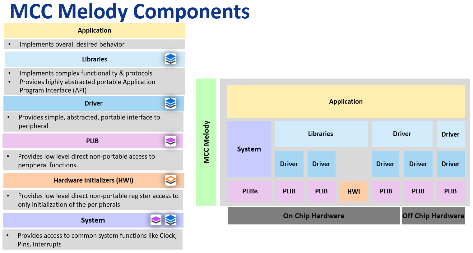
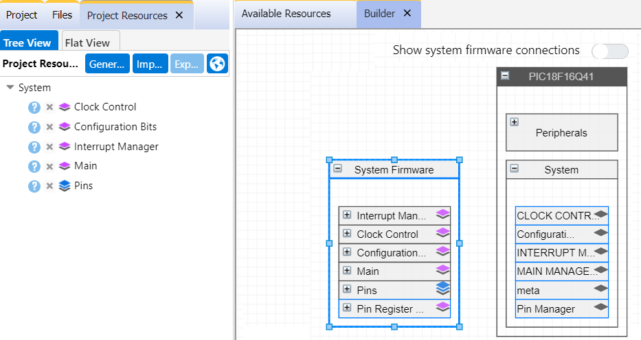
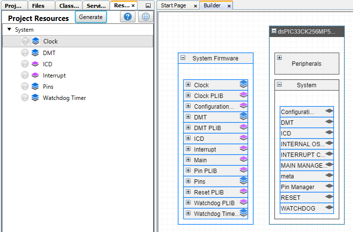
The MCC melody components show in Device- and Project-Resources as follows. Icons indicate the degree of separation from the microcontroller hardware, presented as the black layer at the bottom. The more layers, the more independent the component is from the microcontroller’s hardware.
Hardware independence facilitates portability in the following ways:
- Configuration portability: A use-case-focused configuration interface gives the ability to select/easily change a component's underlying hardware dependency.
- Firmware portability: Writing application code using portable interface API ensures that it's easy to change a peripheral instance the code runs on.
| Component Category | Example | Description |
|---|---|---|
 |
 |
Libraries provide one of the following:
|
|
 |
Drivers support both Configuration and Firmware portability, providing an easy-to-read and efficient abstraction to the functionality of the peripheral, e.g., UART, I2C Host, I2C Client, etc. |
 |
 |
Peripheral Libraries (PLIB) may provide firmware portability, but in general, only a non-portable interface to peripheral functionality |
 |
 |
Hardware Peripherals (Initializers) provide non-portable direct access to peripherals and their registers. As the name suggests, only an initialization function is generated. |
4.1 Libraries
Implement complex "Middleware" functionality, such as protocols, providing a highly abstracted portable application program interface.
Configuration
Libraries can be selected from Device Resources to be made available in Project Resources.
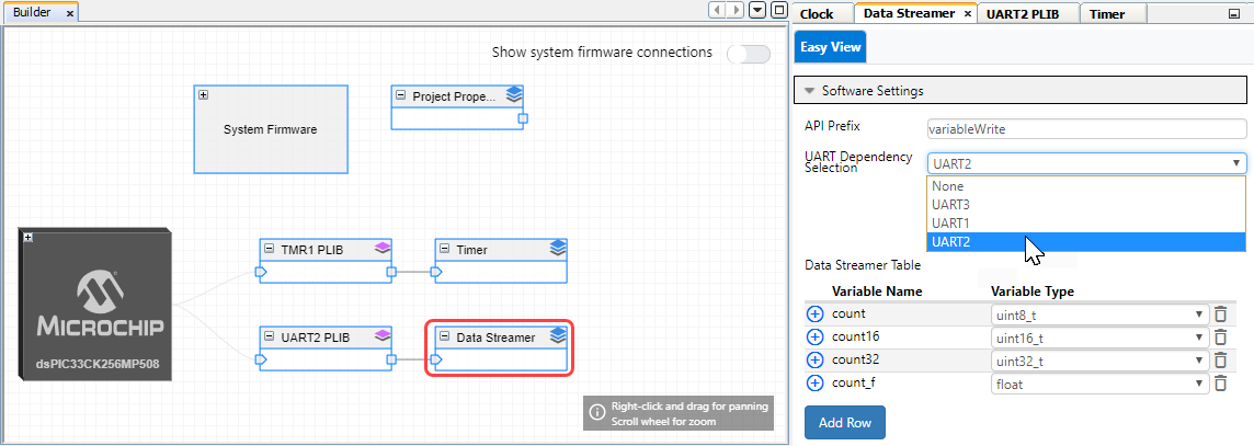
The Easy View for Libraries relates to software configuration settings, i.e., will not have anything to do with registers for hardware peripheral or off-chip components. For example, the Data Streamer Library implements the Data Stream Protocol needed to plot multiple variables on the MPLAB Data Visualizer. Its configuration is a list of variables and their respective types.
Generated Firmware
Libraries provide a portable interface that can be ported to multiple MCU devices.
4.2 Drivers
Drivers support both Configuration and Firmware portability, providing an easy-to-read and efficient abstraction to the functionality of the peripheral, e.g., ADC, UART, Timer, etc. It also includes off-chip drivers, e.g., SPI-based ADC.
Configuration
Drivers can be selected from Available or Device Resources and be made available in Project Resources.
The Drivers provide an abstracted configuration interface. In the Timer Driver example below, one chooses the Timer hardware instance to run the Timeout functionality.
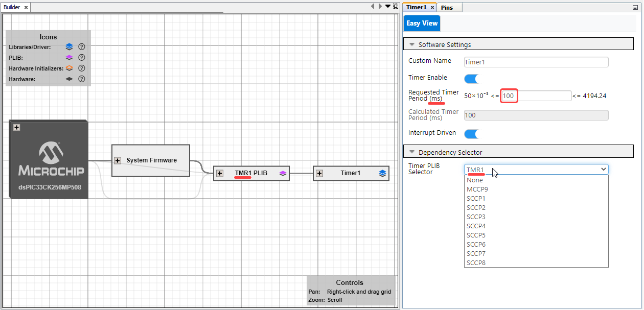
- SCCP*: Single Capture/Compare/PWM
- MCCP**: Multiple Capture/Compare/PWM
Generated Firmware
Drivers and Libraries may provide a portable interface consistent across different MCU devices. So, one is able to have a very similar interface to very different hardware peripherals. The interface will be provided in the form of a driver_interface.h file, containing a DRIVER_INTERFACE struct, which in this example defines the portable interface associated with the timer. In the image below, TMR_INTERFACE defines the portable interface associated with the timer.
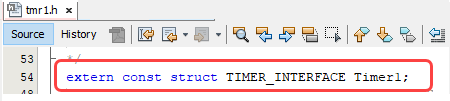
First, initialize the pointer to point to the address of the structure itself, then the interface API can be accessed as structure members. See pointers to structures.
ptrName = &structVariable;
ptrName —> memberName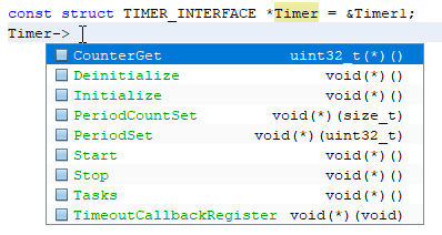
An example application-level code for the dsPIC33CK is listed below, showing the use of the TimeoutCallbackRegister API from the Timer Interface.
#include "mcc_generated_files/system/system.h"

void Timer_Callback_100ms(void){
    LED_Toggle();
}

/*
    Main application
*/
int main(void)
{
    SYSTEM_Initialize();
    Timer->TimeoutCallbackRegister(Timer_Callback_100ms);
    while(1){}
}
4.3 PLIBs (Peripheral Libraries)
Peripheral LIBraries (PLIB) provide a non-portable functional interface to the
peripheral functionalities in the form of an API to support peripheral functionality.
Selection and Configuration
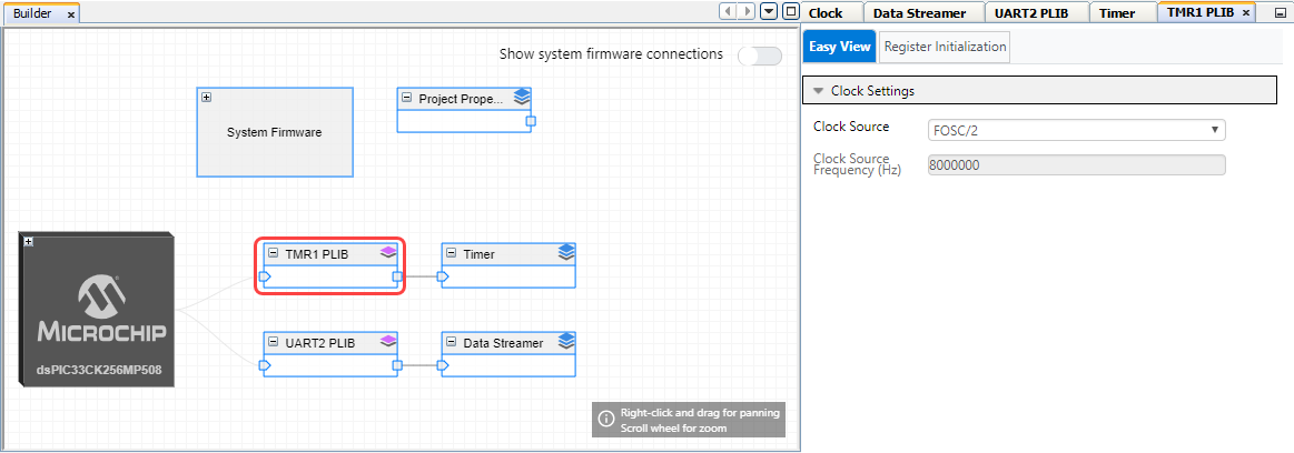
For most Peripheral Drivers, the PLIBS are automatically selected and added to the Project. The PLIBs provide a non-portable interface and are only accessible from the Builder view when the corresponding driver is added to the Project Resources. They are hidden from the Device Resources, Project Resources.
Some of the PLIBs might be available to be selected from the Device Resources.
The PLIBs can provide an Easy View to allow you to configure device-specific settings, which is optional, and PLIBS can choose not to provide that.
Generated Firmware
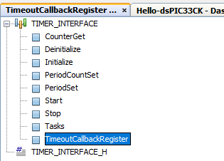
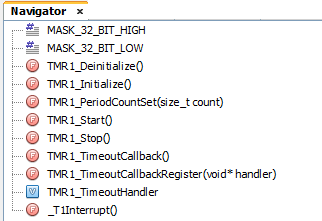
The PLIBs provide a fully functional interface for the peripheral functionality, but which is not fully provided by the Driver. In the image below, one can see the MPLAB X IDE Navigator view of the generated API.
4.4 Hardware Peripheral Initializers
Hardware peripherals provide non-portable direct access to peripherals and hardware
registers. For bare metal development, it is useful if you only want to set up the peripheral
but write your functions. The Hardware Peripheral Initializers allow for:
Configuration
The initializer can be selected from Available or Device Resources and be made available in Project Resources.

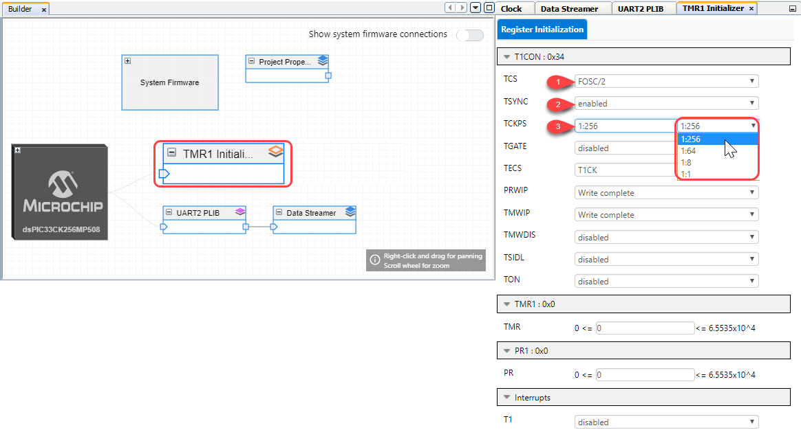
The Initializers allow for Register Initialization, using the bit and register fields, as shown below.
Generated Firmware
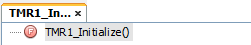
A single function which initializes the peripheral <PERPHERAL>_Initialize( ) i.e., TMR0_Initialize( ); is generated.
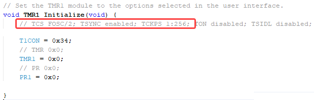
The Initialize function has code comments to describe the settings made.
- T1CON: TCS FOSC/2
- T1CON: TSYNC: Enabled
- T1CON: TCKPS 1:256
The TMR1_Initialize function corresponding to the above configuration is shown below. Note how the configured settings are described in the generated comments.
4.5 System Drivers
Provides system-level core functionality, like Clock, Interrupt and Pins. Some of these can be device-dependent.
- Configuration Bits: Set up the clock source for the system clock, whether or not the watchdog timer is enabled, etc.
- Clock Control (System Clock): Besides clocking the CPU, the main system clock (or a scaled version of this) it is often used to clock peripherals.
Root Level Files
| File Name | What Is in the File |
| system | Here, all the system peripherals are generated |
| system/system.h |
API declaration for initializing the Hardware peripherals, Drivers, and Libraries in the project. This file is called from main.c. |
| system/src/system.c |
API implementation for initializing the Hardware peripherals, Drivers, and Libraries in the project. The SYSTEM_Initialize() function initializes the MCU system (oscillators, clocks, flash wait states, etc.) and peripherals, which have been selected. |
| system/clock.h | API declaration for initializing the clock registers. Automatically called from SYSTEM_Initialize() |
| system/interrupt.h |
Implementations for global interrupt handling. For individual peripheral handlers, refer to peripheral driver [GN-M1] . |
| system/pins.h | API for initializing the pins. Automatically called from SYSTEM_Initialize(). |
| system/src/pins.c | Code for initializing pins |
| driver folder |
Each driver will have a dedicated folder name, which represents the behavior of the peripheral (e.g.: UART, ADC). |
System Initialization
An MCC Melody project, from the start of main( ), will call SYSTEM_Initialize();
This function, in turn, will call functions that initialize various system drivers and any other drivers which are added to the project.
void SYSTEM_Initialize(void)
{
    CLOCK_Initialize();
    PIN_MANAGER_Initialize();
    INTERRUPT_Initialize();
    Peripheral1_Initialize();
    Peripheral1_Initialize();
}
Pin Interface
Three configuration screens handle pin configuration: Pins View, Pins Package view, and Pins Grid View.
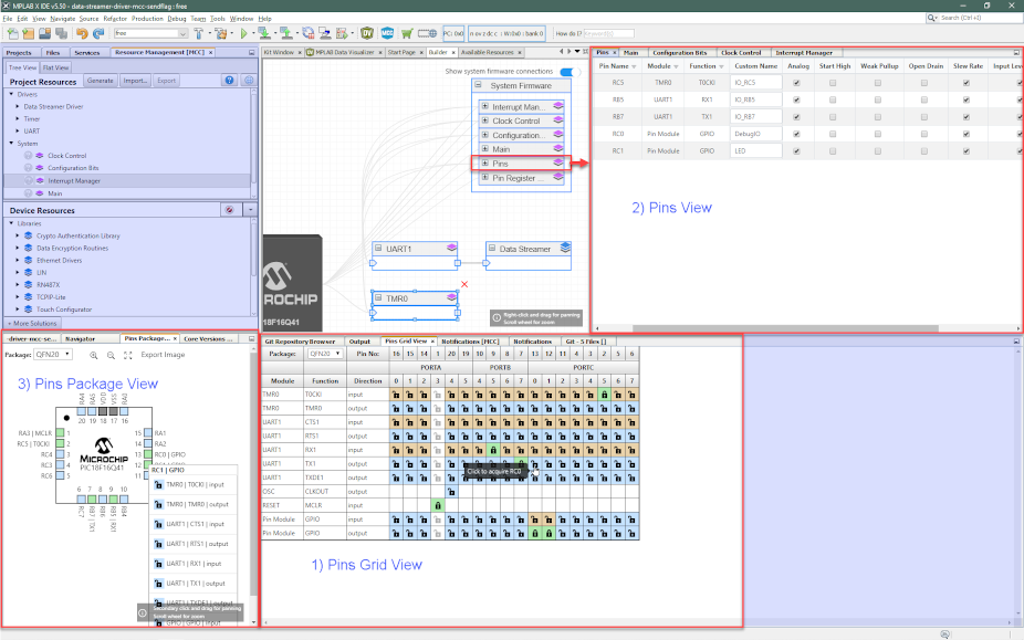
Pins Grid View
The Pins Grid View provides a clear overview of the pin configuration. As new peripherals are added, additional rows are added for each aspect of functionality to which pins need to be assigned.
- Tooltip is made dynamic that gives applicable information for guiding the user
- By default, the Locked Pins Tooltip highlights the API name
- User is allowed to make any pin selection. If a conflicting selection is made, it’ll be notified under the Notifications Tab
Pins View
After a specific pin has been assigned, either in Pins Grid View or Pins Package View, other pin aspects can be configured here. This pin functionality includes setting the pin as default high/low after initialization, enabling an internal pull up or associated interrupt options (e.g., falling edge), etc.
- Columns now support additional pin attributes based on individual device families of PIC and AVR (i.e., Location, Slew Rate, Input Level Control)
- Pin attribute headers are made more descriptive (e.g., OD > Open Drain, WPU > Weak Pullup)
- Location attribute column is added that shows the physical pin location in the package
- Sorting of column headers is provided for necessary attributes like Location, Pin Name, Module and Function
Pins Package View
- The position is changed to the bottom left, adjacent to Versions Panel
- Package can now change from both Package View and Grid View
- Mouse scroll supports smooth zoom in/out
- Secondary/Right click supports panning/drag
- Additional Zoom-In/Out buttons are provided in the toolbar for easy navigation and step-wise zoom
Interrupt/Callback Interface
The interrupt manager functions as an indexing page, like a list of all peripheral interrupts.
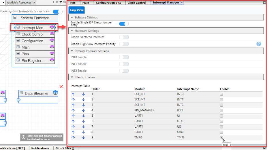
The ISR is typically used to clear interrupt flags, then set the associated callback function, ensuring to keep the ISR sufficiently short to reduce the likelihood of interrupts interrupting each other and the appurtenant complexity of handling this safely.
A default overflow callback is provided (see the example below from tmr0.h). If you would like to place the callback at a specific place in your application (e.g., in main.c), it is then recommended to use the DriverXCallbackRegister() function, e.g., Timer.TimeoutCallbackRegister(Callback_name);
4.6 Firmware Development and Usage Models
MCC Melody supports higher-level development based on portable Libraries and Drivers to very low-level-device specific development based on PLIBs (Peripheral LIBraries) and Hardware Peripheral Initializer-based.
Throughout the entire range of applications, advanced capabilities are built upon fundamental support, and developers can scale projects up or down in complexity and capability without needing to extensively rewrite existing code, as often happens in an embedded environment.
This approach of utilizing cumulative capabilities provides the freedom to choose the development model that best serves the application’s needs, as represented in the figure.
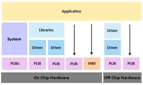
Library Usage Model
MCC Melody libraries support complex and key technologies such as industry-leading Bootloaders, MQTT, USB Host, Device capabilities, etc.
Libraries are built upon MCC Melody drivers and system implementations and isolated from hardware details, allowing the same great library to work with several MCC Melody-supported devices. Generally, libraries are dependent on Drivers. See image above.
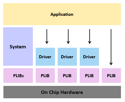
Driver Usage Model
MCC Melody provides seamless portability, interoperability, and peripheral and resource sharing with extremely minimal overhead and is easy to read. So, MCC Melody provides advanced capabilities such as a higher level of abstraction that gives better hardware independence at a low cost.
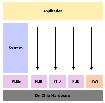
PLIB Only Usage Model
Many developers prefer easy and direct control over peripherals. To support this model, a developer can use the MCC Melody to add additional peripheral libraries (PLIBs) to a project to generate device-specific code to initialize and control the selected peripherals. Again, the application developer must implement much of the logic, as shown by the block diagram below.
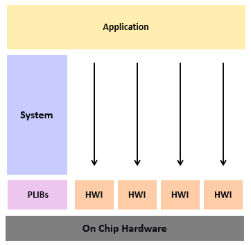
Initialization Only Usage Model
This support can be used to initialize basic functionality necessary to use the device. The application developer must create all additional logic when using MCC Melody to generate only minimal device configuration code, including any further peripheral control logic and potentially complex middleware. As shown by the diagram below, all additional code effectively becomes part of the application.
Usage Model Examples
EEPROM Driver
- The external EEPROM Driver uses the SPI Driver interface to implement the EEPROM-specific functionality, without any direct knowledge of the SPI hardware
- The SPI Driver uses the SPI PLIB to access the hardware features
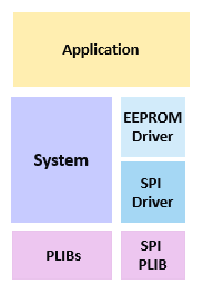
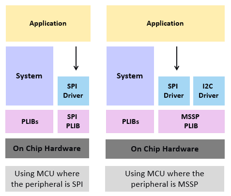
SPI Driver
- SPI functionality can be provided by an SPI or an MSSP** peripheral
- The SPI driver provides an abstraction that works with either an SPI or an MSSP hardware peripheral
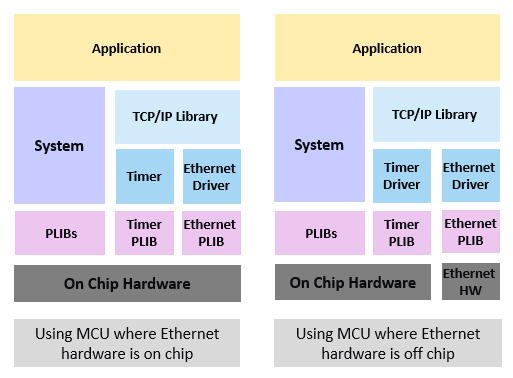
Ethernet Driver
- Ethernet can be an MCU peripheral (on-chip) or can be provided via off-chip hardware
- The Ethernet Driver will be independent of the hardware and provide an abstraction to the TCP/IP Library
- The PLIB will be specific to the ethernet hardware